
Introduction
Modern aircraft are built on composites. The Boeing 787 is 50% composite by weight, the Airbus A350 is 52%, and the F-35 airframe is approximately 35%. That's the baseline for current-generation platforms, not an emerging trend.
The problem is that composites fail differently than metals. Delaminations form between plies, disbonds develop at bondlines, and porosity clusters within laminates — often with zero visible surface indication. FAA AC 20-107B explicitly recognizes that impact damage "often produces subsurface interply delaminations while leaving no external surface demarcations." You can't see what's failing.
Those hidden failure modes make composite NDT both difficult and non-negotiable. This guide walks inspection engineers and NDT technicians through three primary methods — Phased Array Ultrasonic Testing (PAUT), active infrared thermography, and visual/tap testing. Each section covers setup, execution, interpretation, and the errors most likely to produce false accepts.
Key Takeaways
- Composites fail internally; visual inspection alone cannot clear a safety-critical structure
- Three primary methods: PAUT (depth sizing), active thermography (large-area screening), and visual/tap (surface triage)
- Active thermography inspects up to 8–10× faster than ultrasound — no couplant, no contact required
- All dispositions must reference the OEM structural repair manual (SRM) and applicable allowable damage limits (ADLs)
- Top operator errors: calibration block mismatch, coupling dropout, and confusing surface thermal artifacts with structural defects
What You Need to Inspect Aerospace Composites
Composite NDT is not method-agnostic. Choosing the wrong approach for a given part geometry or defect type creates systematic blind spots, not occasional misses. Method selection, surface condition, and equipment calibration all directly affect whether subsurface defects are detected or missed.
Core Tools by Method
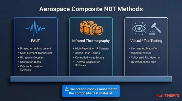
| Method | Key Equipment |
|---|---|
| PAUT | 16- or 32-element phased array instrument, 1–10 MHz transducer, water/gel couplant, calibration reference block, C-scan software |
| Infrared Thermography | MWIR or LWIR IR camera, flash lamps or modulated heat source, data acquisition and analysis software |
| Visual / Tap Testing | Illuminated magnifier, borescope, tap hammer or calibration coin, portable UV lamp |
One calibration point that trips up a lot of programs: reference blocks must be made from the same or equivalent composite material as the part under test. Calibrating on aluminum or generic plastic and then scanning CFRP introduces acoustic impedance mismatch that produces unreliable sensitivity and velocity settings. Skipping this step doesn't introduce minor error — it invalidates the calibration entirely and can cause real defects to fall below the detection threshold.
Setup and Preconditions
Before any scan begins:
- Surface condition: Clean, dry, and free of paint or sealant layers that block UT coupling or alter thermographic emissivity
- Thermal equilibrium: Parts must reach ambient temperature before thermographic inspection — no direct sunlight, no recent handling that introduced localized thermal gradients
- Immersion UT: If using water-coupled immersion scanning, the part must be fully submerged with no air bubble entrapment at the surface
- Environment control: Shield ambient IR sources (windows, nearby hot equipment) that could contaminate thermographic background frames
NDT Methods for Aerospace Composite Inspection
For critical aerospace structures, two complementary methods are often used in sequence: thermography for large-area screening, followed by PAUT for precise defect sizing and depth confirmation. Each method has a defined role — no single technique covers all scenarios.
Method 1: Phased Array Ultrasonic Testing (PAUT)
PAUT transmits high-frequency sound waves into the composite laminate and analyzes reflected or transmitted signals to locate and size internal discontinuities. C-scan imaging produces a two-dimensional map of defect location and depth.
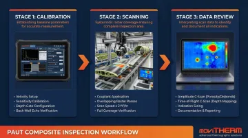
The inspection sequence:
- Calibration — Using an OEM-approved composite reference standard, calibrate for velocity, sensitivity (amplitude gate), and depth (time-of-flight gate), verifying that back-wall echoes are visible and flat-bottom hole reflectors read at the required amplitude.
- Scanning — Apply couplant or set up water-jet coupling. Scan using overlapping or encoded raster passes per the inspection procedure. Maintain consistent transducer pressure and scan speed — FAA-funded testing found that rates exceeding approximately 2 ft²/hr correlated with decreased detection reliability.
- Data review — Review amplitude and time-of-flight C-scans side by side. Amplitude C-scans reveal energy-absorbing defects (porosity, disbonds); ToF C-scans reveal depth position. Document any indication exceeding the gate threshold with location, size, and estimated depth.
PAUT delivers excellent depth information and defect sizing capability, and is accepted by Boeing, Airbus, and Spirit Aerosystems specifications. POD[90/95] for delaminations in 12–32 ply CFRP laminates is approximately 0.91 inches when inspection aids are used. The tradeoff: it requires couplant, trained certified operators, and is slower than thermography for large-area coverage.
Method 2: Active Infrared Thermography
Active thermography introduces a controlled thermal stimulus (a flash pulse for pulsed thermography, or modulated heat for lock-in thermography) and uses an IR camera to map the resulting surface temperature distribution over time. Subsurface defects interrupt heat flow and appear as localized thermal anomalies.
In practice:
- Setup — Position the IR camera and excitation source at the standoff distance specified in the procedure. Verify the part surface is clean and at thermal equilibrium.
- Excitation and acquisition — Trigger the flash pulse or initiate modulated heating at the specified frequency. Acquire thermal image sequences at the camera's full frame rate for the procedure-specified duration (typically 1–10 seconds for pulsed, longer for lock-in).
- Analysis — Apply signal processing to the thermal sequence: Thermal Signal Reconstruction (TSR), Pulse Phase Thermography (PPT), or phase analysis. TSR significantly reduces noise and generates time-derivative images with enhanced sensitivity to smaller defects; PPT minimizes effects of non-uniform heating across large panels.
MoviTHERM's C-CheckIR system covers 430 × 340 mm (17 × 13 inches) per measurement at a 400 mm standoff distance, with inspections completing in seconds. The C-CheckIR Sensor is purpose-built for inline production environments, integrating directly with robotic scanning systems and MES software. Customers including Boeing, Airbus, Lockheed Martin, and Sikorsky have deployed these systems; one NDT professional at Quatro Composites reported inspection time improvements of 8–10× compared to ultrasound.
One hard limit to plan around: flash thermography depth penetration in CFRP is generally limited to approximately 1.5–2.0 mm from the inspection surface. For deeper defects in thick laminates, PAUT is the required complement. The governing standard, ASTM E2582-21, covers infrared flash thermography of composite panels and repair patches in aerospace applications.
Method 3: Visual Inspection and Tap Testing
Visual inspection identifies surface-breaking and near-surface anomalies through trained observation. Tap testing uses the audible and tactile response to a coin or tap hammer to detect shallow disbonds and delaminations ; a dull or hollow sound indicates loss of laminate consolidation.
How it works:
- Visual survey — Under adequate illumination, systematically scan 100% of the accessible surface area at a defined distance and angle. Document all surface anomalies, their location relative to reference datums, and approximate size.
- Tap testing — Using a smooth-faced tap hammer or coin, lightly and systematically tap across the area of interest. A crisp, high-pitched response indicates a well-bonded laminate; a dull, hollow response indicates subsurface disbonding.
- Documentation and escalation — Mark anomalies found; determine whether volumetric follow-up (UT or thermography) is needed to establish defect depth and size before disposition.
Ultrasonic-based tap devices achieve POD[90/95] of approximately 0.78 inches for focused go/no-go inspections. Tap testing is a screening tool only: it cannot provide the quantitative depth or sizing data required for structural disposition.
How to Interpret Your Inspection Results
Misinterpretation has direct airworthiness consequences. A coupling dropout dismissed as a scan artifact may be a real delamination. A defect mis-sized as minor can grow under cyclic loading.
All dispositions must reference the applicable OEM structural repair manual (SRM), allowable damage limit (ADL) document, or engineering disposition.
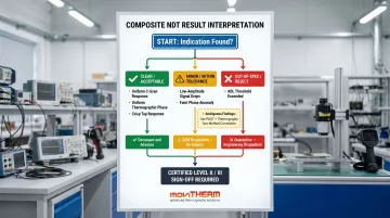
Reading Your Results
Clean / Acceptable:
- PAUT C-scan: Uniform back-wall amplitude, no localized amplitude drops or ToF shifts
- Thermographic phase image: Uniform phase response across the panel, no localized anomalies
- Tap test: Consistent crisp sound across all tapped areas
Action: Document as conforming, record in inspection log, advance part.
Minor / Within-Tolerance Indications:
- PAUT: Low-amplitude drops not extending through-thickness, below ADL threshold
- Thermography: Faint, low-contrast phase anomalies within allowable size limits
Action: Apply OEM disposition (monitor, blend, or cosmetic repair per SRM), document indication, schedule re-inspection at next interval.
Out-of-Spec / Reject:
- PAUT: Amplitude drop exceeding ADL gate threshold, or through-thickness delamination on B-scan cross-section
- Thermography: High-contrast thermal anomaly with diffusion pattern consistent with a void or disbond
- Tap test: Dull response covering an area exceeding the allowable limit
Action: Immediately quarantine the part. Initiate engineering disposition. Escalate to structural repair or scrap per the SRM. Never return an out-of-spec composite part to service without documented engineering sign-off.
When findings are ambiguous or fall near acceptance limits, don't disposition on a single method. Use two-method correlation (PAUT + thermography) to cross-validate before making a call. Only a certified Level II or Level III NDT inspector holds final accept/reject authority — no disposition is complete without their sign-off.
Common Errors in Aerospace Composite Inspection
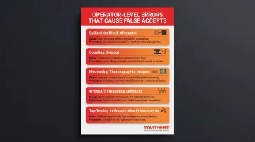
The failures below account for the majority of missed defects and false accepts in composite NDT programs. Each has appeared in FAA-documented assessments — and all are operator-level errors that proper procedure and equipment setup can prevent.
Calibration block mismatch: Calibrating a PAUT system on an aluminum block and then scanning CFRP produces incorrect velocity and sensitivity settings. The calibration standard must match the test article in material type, thickness, and layup — and bonding method matters too. Secondarily bonded substructures generate more signal noise than co-cured ones, which directly affects POD results.
Coupling dropout: In contact UT, lifting the probe or allowing air between the transducer and surface produces the same signal as a large-area delamination. Re-probe any area where coupling consistency is uncertain before logging an indication. FAA trials found that freehand scanning without coverage aids degraded POD[90/95] from 0.91 to 1.75 inches — a significant accuracy loss.
Misreading thermographic images: Surface paint variations, fastener shadows, and edge effects can mimic defect indications in pulsed thermography. Without TSR or PPT processing — and a working understanding of the material's thermal diffusivity — operators report surface artifacts as defects, or miss real delaminations buried under surface noise.
When surface uniformity is a concern, lock-in thermography is the better choice. It reduces sensitivity to emissivity variations that trip up pulsed methods.
Wrong UT frequency selection: Low frequencies miss shallow near-surface defects; high frequencies attenuate rapidly in thick laminates. ASTM E3370-22 specifies a frequency range of 0.5–20 MHz for aerospace composite applications — frequency selection must match laminate thickness.
Tap testing in uncontrolled environments: Inconsistent strike force or background shop noise makes reliable sound discrimination impossible. If you can't control the environment, skip tap testing and escalate directly to volumetric inspection.
Safety and Best Practices
Precautions specific to aerospace composite NDT — often absent from standard procedure documents:
- Keep personnel clear of the direct optical path during flash discharge — flash excitation hazards are underreported in standard thermography SOPs
- CFRP dust: Wear nitrile gloves and respirators when handling cut or machined parts — NASA guidance classifies carbon fiber dust as an eye, skin, and respiratory irritant (ACGIH TLV-TWA: 10 mg/m³ total, 3 mg/m³ respirable)
- Lockout/tagout: Apply to any part removed from an energized system before beginning inspection
- Couplant contamination: Remove all residual couplant gel before any subsequent bonding operation — contaminated bondlines are a structural defect waiting to happen
- Personnel qualification: All inspections must be performed by NAS 410 / EN 4179-qualified personnel; final dispositions require a Level II or Level III certified inspector's signature
- Nadcap accreditation: AC7114/AC7114S accreditation is typically required for Tier 1 suppliers — confirm supplier scope before awarding inspection contracts
Conclusion
The strongest composite inspection programs don't rely on a single method. Visual and tap testing provide rapid surface screening. Active thermography covers large areas volumetrically without contact — MoviTHERM's C-CheckIR and C-CheckIR Sensor systems bring this capability to both field inspection and inline production environments. PAUT provides the depth characterization and defect sizing required for structural disposition.
Reliable inspection depends equally on proper setup, calibrated equipment, correct method-material matching, and certified interpretation. Composites' damage tolerance can mask developing defects until failure. Shortcuts at any stage in the inspection workflow introduce risk that doesn't surface until it's costly.
If your current NDT workflow relies on a single method or uses contact UT for all large-panel screening, active thermography integration deserves a direct evaluation. For programs running high part volumes, the cycle time reduction is measurable — inspections that take hours with contact UT routinely complete in minutes with flash thermography.
Frequently Asked Questions
Frequently Asked Questions
What NDT methods can be used for composite inspection?
Primary methods include visual inspection, tap testing, ultrasonic testing (contact PE and PAUT), infrared thermography (pulsed and lock-in), radiographic testing (RT/CT), shearography, and acoustic emission — ten method categories total per ASTM E2533-21. Selection depends on defect type, part thickness, geometry, and required throughput.
How is NDT used in aerospace?
NDT covers every stage of the aerospace lifecycle: manufacturing quality control, incoming material inspection, MRO in-service checks, and post-event damage assessment (impact, lightning strike, hard landing). Regulatory and OEM requirements mandate certified procedures for all safety-critical structures, with dispositions referenced to the applicable SRM or ADL document.
What defects are most common in aerospace composite structures?
Delamination, porosity, disbonds, voids, barely visible impact damage (BVID), and matrix cracking are the most frequently encountered defect types. Many have no visible surface indication — FAA AC 20-107B explicitly notes that impact damage can produce subsurface delaminations with no external surface demarcations, which is why volumetric NDT is required.
Is infrared thermography effective for inspecting thick composites?
Active thermography works well for thin-to-medium laminates. Depth sensitivity degrades with thickness, and penetration in CFRP is generally limited to approximately 1.5–2.0 mm. For thick structures requiring deeper volumetric characterization, PAUT is the preferred complement.
How do I choose the right NDT method for my application?
Start with the defect type and geometry. Use thermography for fast large-area screening of skins and panels, PAUT for thick structures requiring depth sizing, and visual/tap for accessible surfaces and in-field MRO. For critical structures, run thermography first for broad coverage, then PAUT to confirm and size any indications found.
What standards govern composite inspection in aerospace?
NAS 410 / EN 4179 govern NDT personnel qualification. ASTM E2582-21 covers infrared flash thermography of composite panels; ASTM E2533-21 is the guide for NDE of polymer matrix composites. OEM process specifications (Boeing DPS 4.738-2, Airbus AITM 6-4002) apply at the program level. Nadcap accreditation under AC7114/AC7114S is typically required for Tier 1 suppliers performing NDT on aerospace composite structures.