Infrared cameras make those warnings visible. By detecting thermal anomalies non-contactly on live, energized equipment, they let maintenance teams catch developing faults before unplanned downtime or safety incidents occur.
That said, pointing a camera at equipment and reading results isn't straightforward. Results vary significantly based on camera selection, emissivity settings, load conditions during inspection, and how findings feed into maintenance workflows. This guide covers the full process.
Key Takeaways
- Infrared cameras detect heat anomalies without contact, identifying failing electrical connections, worn bearings, and process equipment problems early
- The U.S. DOE FEMP guide credits predictive maintenance programs with 10x ROI, 35–45% less downtime, and 25–30% lower maintenance costs
- Effective programs require baseline images under consistent load, correct emissivity settings, and findings integrated into a CMMS
- Fixed continuous monitoring suits critical assets; route-based inspection suits periodic checks on lower-priority equipment
- Four variables — emissivity, load level, camera resolution/NETD, and distance-to-target — determine whether you catch real faults or get misleading readings
How to Use Infrared Cameras for Predictive Maintenance
Step 1: Identify and Prioritize Equipment for Inspection
Start with your CMMS or maintenance asset list. Flag equipment where failure creates safety risk, unplanned downtime, or significant production loss — these get inspected first and most frequently.
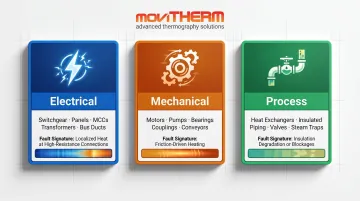
Categorize assets by failure mode:
- Electrical: Switchgear, panels, motor control centers, transformers, bus ducts — faults appear as localized heat at high-resistance connections
- Mechanical: Motors, pumps, bearings, couplings, conveyors — faults show as friction-driven heating in bearings or misaligned drives
- Process: Heat exchangers, insulated piping, valves, steam traps — faults present as insulation degradation or blockages disrupting normal temperature patterns
Each category also has distinct inspection positioning requirements and alert thresholds — factor these into your inspection plan from the start.
Step 2: Capture Baseline Thermal Images
Every future inspection depends on this step. Inspect each priority asset under stable, normal operating conditions and document baseline thermal images. Without them, trending over time is impossible — you have no reference point for "normal."
Record the following for every baseline image:
- Emissivity value used
- Reflected temperature compensation setting
- Distance from camera to target
- Lens used
- Ambient temperature and load condition at time of capture
Future inspections must replicate these conditions exactly. A baseline captured at 80% load compared to a follow-up at 30% load produces meaningless data.
Step 3: Set Alert Thresholds and Decide on Monitoring Mode
Alert Thresholds
For electrical equipment, NETA MTS TABLE 100.18 provides the widely adopted severity framework:
| Priority | Delta-T Between Similar Components | Recommended Action |
|---|---|---|
| 1 | 1°C – 3°C | Possible deficiency; investigate |
| 2 | 4°C – 15°C | Probable deficiency; repair as time permits |
| 3 | >15°C | Major discrepancy; repair immediately |
NFPA 70B 2023 (now a mandatory standard, not a recommended practice) uses nearly identical thresholds and requires thermographic inspection of all electrical equipment at least every 12 months.
Monitoring Mode
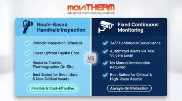
Two approaches, each with a distinct use case:
- Route-based handheld inspection: Appropriate for secondary assets inspected periodically. Lower upfront cost, requires trained thermographer on scheduled routes
- Fixed continuous monitoring: Appropriate for critical assets requiring 24/7 surveillance. Automated alerts without manual intervention
MoviTHERM's iTL Monitoring Platform supports fixed continuous monitoring with automated alerts via text, voice, and email — with locally triggered alarms at the gateway immediately upon threshold breach, independent of cloud update rates.
Step 4: Conduct Inspections and Compare Against Baseline
During each inspection, compare thermal images against documented baselines. Look for:
- Hot spots that weren't present in the baseline
- Asymmetric heating in components that should be uniform
- Gradual temperature trends rising over multiple inspection cycles
Sudden spikes require immediate action. Gradual rises should trigger scheduled maintenance planning; they're often more valuable as early warnings than acute events.
Safety requirements during electrical inspections:
- Equipment must be at or above 40% of rated load (NFPA 70B 2023 and NETA both require this minimum)
- Electrical enclosures must be open or equipped with IR-transparent windows
- All applicable PPE per NFPA 70E must be used before approaching energized equipment
- IR windows allow inspection without opening enclosures, keeping arc flash exposure below the 1.2 cal/cm² threshold that triggers arc-rated clothing requirements
Step 5: Document Findings, Assign Severity, and Generate Work Orders
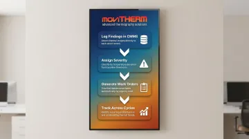
Findings that don't enter a maintenance workflow don't get fixed. After each inspection:
- Log all findings in the CMMS with thermal images attached
- Assign severity based on temperature deviation from baseline and applicable thresholds
- Generate work orders prioritized by urgency
- Track findings across multiple cycles to identify recurring problem areas or accelerating trends
Recurring faults in the same location often point to a systemic issue: overloaded circuits, chronic misalignment, or inadequate lubrication. A single corrective repair won't resolve the root cause.
What You Need Before Starting an IR Predictive Maintenance Program
Equipment and Camera Requirements
Industrial predictive maintenance applications use LWIR (8–14 µm) uncooled microbolometer cameras as the standard. Key specifications to match to your application:
- NETD (Noise Equivalent Temperature Difference): Below 50 mK for detecting subtle temperature differentials in early-stage faults. MoviTHERM supplies cameras meeting this threshold across FLIR and Optris lines — the FLIR A50/A70 series achieves <35–45 mK; the Optris PI 640i LT delivers 40 mK
- Resolution: Match to the smallest feature you need to resolve at your working distance. Small electrical components at close range tolerate moderate resolution; large rotating equipment or wide-area scanning needs higher pixel counts
- Spectral range: 8–14 µm LWIR covers the vast majority of industrial PdM applications
MoviTHERM sources from FLIR, Optris, and others, so camera selection is matched to your application — not limited to what a single vendor offers. That multi-brand access regularly prevents both overbuying on specs you don't need and under-specifying for the conditions you have.
Inspection Conditions and Access Requirements
Camera hardware is only part of the equation. Conditions at inspection time determine whether results are valid:
- Minimum 40% of rated load: Required by both NETA and NFPA 70B 2023. Below this threshold, high-resistance connections and worn bearings may not generate sufficient heat to produce a detectable signature
- Enclosure access: Electrical panels must be open or fitted with IR-transparent windows for accurate readings
- Environmental factors: Outdoor inspections must account for wind, solar loading, and ambient temperature variation — all of which affect apparent surface temperatures
Operator Training and Compliance Readiness
Thermographers need to understand more than how to operate a camera. Accurate results require:
- Emissivity values for common industrial materials
- Reflected temperature compensation settings
- Thermal pattern interpretation by equipment type
- Understanding of load conditions and their effect on heat signatures
ITC certification follows a three-tier structure (Level I through III) aligned with ASNT SNT-TC-1A guidelines. Level I qualifies operators to follow written procedures and identify anomalies; Level II adds root cause analysis; Level III covers program management.
At minimum, Level I certification is required for inspection records to hold up under audit, insurance review, or regulatory scrutiny. ASTM E1934-99a (reapproved 2024) remains the active standard guide for examination methodology and documentation requirements.
Key Variables That Affect Infrared Inspection Accuracy
Even a quality camera produces misleading results if these four variables aren't controlled. Most false negatives and false positives in IR predictive maintenance programs come from here, not from camera hardware.
Emissivity
Emissivity is the ratio of infrared energy a surface emits relative to a perfect blackbody (value of 1.0). Setting the wrong value causes the camera to calculate an incorrect surface temperature.
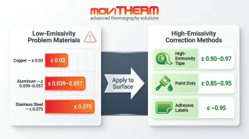
Polished metals are the common problem: aluminum (0.039–0.057), copper (0.03), and stainless steel (0.075) all have very low emissivity and reflect ambient IR radiation — making them appear hotter or cooler than they actually are.
Practical fix: apply one of the following to low-emissivity components before imaging to create a reliable measurement point without altering the component itself:
- High-emissivity tape (0.90–0.97)
- Paint dots (0.85–0.95)
- Adhesive labels (~0.95)
Equipment Load Level
Thermal anomalies are proportional to load. A loose connection at 10% load may produce a fraction of a degree of temperature rise — below detection thresholds. Both NETA and NFPA 70B 2023 independently specify 40% of rated load as the minimum for reliable fault detection.
That load threshold has a direct scheduling implication: inspections run during off-peak or low-production periods are one of the most common causes of missed defects in route-based programs.
Camera Resolution and NETD
These two specs work together. Resolution determines how small a thermal feature the camera can resolve at a given distance. NETD determines the smallest temperature differential distinguishable from background noise.
For small electrical components at close range, moderate resolution often suffices. For large rotating equipment or wide-area scanning, higher resolution and lower NETD become critical to catching subtle gradients early. A camera with excellent NETD but poor resolution may detect a temperature difference but can't pinpoint its source.
Distance-to-Target Ratio
Each lens has an instantaneous field of view (IFOV) defining the smallest measurable area at a given distance. Imaging from too far away averages temperature across a larger area, diluting hot spot readings for small defects.
The practical rule: verify that the target covers at least 3×3 pixels (9 pixels) in the image — the minimum needed for 90% measurement energy accuracy. If it doesn't, move closer or use a telephoto lens.
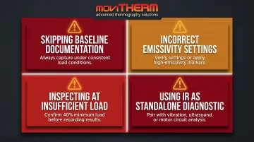
Common Mistakes When Using Infrared Cameras for Predictive Maintenance
Skipping baseline documentation: Without a documented baseline under consistent conditions, you can't distinguish a new fault from normal operating variation. Load differences, ambient temperature shifts, and camera distance variations between sessions all invalidate your comparisons.
Incorrect emissivity settings: Low-emissivity surfaces — bare aluminum, copper bus bars, stainless steel — reflect ambient radiation and produce false alarms or missed faults. Always verify emissivity settings match the material, or apply high-emissivity reference markers.
Inspecting at insufficient load: Electrical panels and motor drives inspected during low-demand periods can show clean thermal images even when faults exist — always confirm the system is at or above the 40% load minimum before calling results normal.
Using IR as a standalone diagnostic: Thermal imaging flags where a problem exists, not what caused it. Pair IR findings with vibration analysis, ultrasound, or motor circuit analysis — and log results in your CMMS alongside other condition monitoring data — to confirm the fault and identify the specific failure mechanism.
Frequently Asked Questions
What is predictive maintenance using thermal imaging?
Thermal imaging predictive maintenance uses infrared cameras to detect heat anomalies in operating equipment. Rising temperatures in electrical connections, bearings, or process components indicate developing faults, allowing scheduled repairs before failure occurs — without shutting down equipment or making contact.
How much does a thermography inspection cost?
Third-party inspections are priced by asset count, facility size, and thermographer certification level. In-house programs require upfront camera investment — fixed monitoring cameras run roughly $1,200 to $10,000+ depending on resolution and sensitivity — offset by long-term savings from avoided failures.
What types of equipment benefit most from infrared camera inspection?
The strongest applications are electrical distribution systems (panels, switchgear, transformers), rotating machinery (motors, pumps, bearings), and process equipment (heat exchangers, insulated piping, valves, steam traps) — anywhere temperature elevation reliably precedes failure.
How often should infrared inspections be performed?
NFPA 70B 2023 mandates thermographic inspection of all electrical equipment at least every 12 months, with equipment in poor condition requiring inspection every 6 months. Fixed camera systems on critical assets provide continuous 24/7 monitoring, eliminating scheduled route requirements entirely for those assets.
What temperature difference from baseline indicates a problem?
Interpretation depends on equipment type. For electrical equipment, NETA MTS classifies a 1–3°C delta between similar components as warranting investigation; above 15°C is a major discrepancy requiring immediate action. Trend direction matters as much as absolute numbers — a temperature rising 2°C per month demands attention even if it hasn't crossed a severity threshold yet.
Can infrared cameras be used while equipment is running?
Yes — non-contact inspection on live, energized equipment is one of the primary advantages of IR thermography. Equipment must be under operating load for results to be meaningful, and NFPA 70E protocols (appropriate PPE, IR windows for closed panels) apply before approaching energized gear.