Introduction
Additive manufacturing unlocks geometries that traditional machining simply cannot produce — internal lattices, conformal cooling channels, topology-optimized structures built layer by layer. That same process, however, buries defects where no visual inspection can reach.
Porosity, lack of fusion, subsurface cracks — these flaws are invisible on the surface and deadly under load. In a turbine blade or orthopedic implant, a void that would pass unnoticed in a non-structural bracket can trigger catastrophic failure.
The consequences reach far beyond the part itself: costly recalls, regulatory non-compliance, and liability exposure in aerospace, defense, and medical markets.
The scale of this risk is substantial. Most manufacturing companies carry quality-related costs equal to 15–20% of total revenue, covering rework, scrap, warranty claims, and recalls — and the global AM industry grew 9.1% to $21.9 billion in 2024, meaning more AM parts are entering safety-critical applications every year.
This guide breaks down what NDT for AM actually involves, which defects it must catch, and how to select the right method for your specific parts and processes.
Key Takeaways
- NDT for AM detects internal defects — porosity, cracks, lack of fusion — without destroying the part, enabling pass/fail decisions that preserve usable components
- AM's complex geometries, surface roughness, and anisotropic microstructures demand AM-specific calibration — standard NDT approaches fall short
- Key methods include X-ray CT, ultrasonic testing, resonance inspection, liquid penetrant testing, eddy current testing, and infrared thermography
- No single method is universally optimal — selection depends on defect type, material, part geometry, inspection timing, and throughput
- Hybrid strategies (fast screening + volumetric confirmation) balance thoroughness with production efficiency
What Is NDT for Additive Manufacturing and Why It Matters
NDT in the AM context is a category of inspection techniques that evaluate structural integrity, material properties, and dimensional accuracy of 3D-printed parts without altering or destroying the component. The part survives the inspection: if it passes, it ships; if it doesn't, it gets analyzed further.
But not all AM parts face the same risks — and that's where inspection strategy gets specific.
AM Processes Create Different Defect Profiles
NDT requirements are not uniform across AM technologies. Each process introduces its own characteristic flaw types:
| AM Process | Primary Defect Risks |
|---|---|
| Selective Laser Melting (SLM) | Gas porosity, lack of fusion, cracking |
| Electron Beam Melting (EBM) | Lack of fusion, trapped powder |
| Directed Energy Deposition (DED) | Incomplete fusion, geometric distortion |
| Binder Jetting | Residual porosity, binder burnout voids |
| Wire Arc AM (WAAM) | Distortion, macro-defects, incomplete fusion |
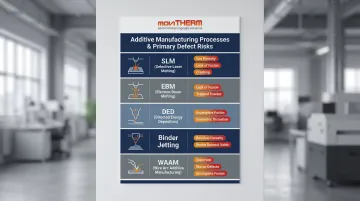
This process-to-defect mapping matters when choosing an inspection strategy. An NDT approach calibrated for SLM titanium parts doesn't apply directly to binder-jetted stainless steel.
Five Reasons AM Parts Require NDT
- Quality assurance — Detects internal defects (porosity, cracks, trapped powder) that compromise mechanical properties before parts reach service
- Cost efficiency — Early detection reduces downstream rework, scrap, and recall exposure; NIST SP 1176 identifies defect detection as the primary AM cost lever
- Material integrity — AM parts exhibit process-dependent microstructures; NDT verifies actual properties match design intent
- Regulatory compliance — NASA-STD-6030 mandates NDT for spaceflight AM hardware; FAA requires qualification evidence for flight-critical parts
- Lifecycle monitoring — Periodic NDT re-inspection detects fatigue-related degradation in service before failure
Common Defects in AM Parts That NDT Must Detect
AM defects are primarily subsurface, invisible to visual inspection and surface-only methods. Knowing how each defect forms points directly to which NDT method can reliably find it.
The Core AM Defect Types
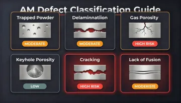
| Defect | Formation Mechanism | Why It's Dangerous |
|---|---|---|
| Gas porosity | Dissolved gas (argon, nitrogen) forms bubbles during solidification | Stress concentration; fatigue initiation |
| Keyhole porosity | Excessive energy density collapses vapor cavity | Irregular voids; high stress intensity |
| Lack of fusion | Insufficient energy to fully melt powder between layers | Planar defects; severe fatigue strength reduction |
| Cracking | Residual stress from rapid thermal cycling exceeds material strength | Catastrophic failure risk |
| Trapped powder | Partially incorporated particles in the melt pool | Reduced density; fatigue life reduction |
| Delamination | Layer-to-layer bond failure from residual stress | Structural integrity loss |
One quantitative threshold worth knowing: research indicates that keeping porosity below 2 vol.% significantly reduces the likelihood of component failure under loading. Above that threshold, fatigue crack initiation probability increases sharply.
Post-Processing Complicates the Picture
Post-processing steps introduce additional inspection complexity that many teams underestimate:
- Hot Isostatic Pressing (HIP) closes most porosity, but X-ray tomography studies confirm that pores containing trapped argon gas can reopen during subsequent high-temperature heat treatments , making post-HIP NDT necessary even when pre-HIP CT showed acceptable results
- Shot peening and machining improve fatigue life but can compress surface-breaking pores and smear material over near-surface defects, making them invisible to penetrant testing
- Improper heat treatment can increase porosity or create undesirable microstructural changes if temperature regimes aren't tightly controlled
The sequencing question of when to inspect relative to surface finishing has a straightforward answer: volumetric methods (CT, resonance) should precede surface finishing, while surface-sensitive methods (PT, eddy current) should follow it.
Defect Criticality Is Application-Dependent
A small void acceptable in a non-structural aerospace bracket may be disqualifying in a turbine blade or orthopedic implant. NDT acceptance criteria must be defined per application and industry standard, not borrowed from general casting or forging specifications.
Key NDT Methods for Additive Manufacturing
Each method detects different defect types, operates under different constraints, and fits different production environments. The goal here is to give engineers the information to evaluate trade-offs rather than default to whichever method they already know.
X-Ray Computed Tomography (CT)
CT provides full 3D volumetric imaging of internal structures — porosity, cracks, lack of fusion, trapped powder, and dimensional deviations. It's the most comprehensive single-method inspection available for AM parts.
Capabilities:
- Detects defects as small as ~5 micrometers in research settings; minimum reliably detectable pore size in production nickel alloy parts is approximately 40 micrometers
- Captures dimensional deviations alongside defect data in a single scan
- Applicable standard: ASTM E1441-11(2017)
Limitations:
- High equipment cost and long scan times (minutes to hours per part)
- Dense metals and large parts require higher X-ray energies, which reduces resolution
- Low throughput makes 100% production inspection impractical for high volumes
CT is the right choice when full volumetric characterization is required and cost is secondary — typically for first-article qualification, process development, or high-value flight-critical components.
Ultrasonic Testing (UT)
UT uses high-frequency sound waves to detect internal flaws including cracks, voids, and lack of fusion. Phased array UT (PAUT) improves performance on complex geometries by steering the beam electronically.
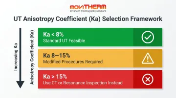
AM-specific challenge: AM parts exhibit anisotropic microstructures oriented along the build direction. In SLM-produced EP648 alloy, transverse wave velocity differences reach 17%, and reflected signal amplitude can vary by up to 4 dB depending on beam direction relative to the build axis. Standard UT procedures developed for wrought materials don't apply directly.
A practical decision framework based on the anisotropy coefficient (Ka):
- Ka < 8%: Standard UT feasible
- 8–15%: Modified procedures required
- Ka > 15%: Standard UT impractical — use CT or resonance inspection instead
UT also requires coupling media (gels) and surface preparation, which creates challenges for as-built AM surface roughness.
Resonance Inspection (RI)
Resonance inspection uses a part's natural vibration frequencies to assess material consistency across the entire component volume. Deviations from the expected resonant signature indicate the presence of a flaw.
Key advantages for AM production:
- Whole-part assessment completed in seconds — orders of magnitude faster than CT
- Non-contact; no couplants or surface preparation required
- Operable by non-certified personnel
- Effective for detecting bulk structural anomalies and process shifts
Critical limitation: RI identifies that something is wrong but cannot localize or characterize the defect. It works well as a production triage tool — flagging suspect parts for confirmatory CT — but not as a standalone solution for defect characterization.
Liquid Penetrant Testing (PT) and Electromagnetic Testing (ET)
These two surface-focused methods work best as supplementary checks alongside volumetric techniques.
Liquid Penetrant Testing (PT):
- Detects surface-breaking cracks and open porosity via dye penetrant
- Low cost and simple to execute
- AM limitation: As-built surface roughness causes excessive penetrant bleed-out and false positives. PT effectively requires machining or polishing before reliable results on AM parts
Eddy Current Testing (ET):
- Electromagnetic induction detects near-surface flaws in conductive materials (stainless steel, titanium, Inconel)
- In-situ ECT at 200 kHz achieves approximately 0.95 mm penetration depth in Inconel 718, resolving porosity increases as small as 0.1% by volume and individual defects as small as 0.3 mm
- Larger-diameter sensors are less sensitive to surface roughness — a meaningful advantage for AM parts
Neither method reaches internal defects. Use them after surface preparation as confirmation of surface integrity, not as primary AM inspection strategies.
Infrared Thermography
Where PT and ET stop at the surface, active thermography goes deeper — without contact, couplants, or ionizing radiation. It applies a controlled thermal stimulus to a part and captures how heat propagates through the material with an infrared camera. Subsurface voids, delaminations, and bonding defects interrupt heat flow and appear as thermal anomalies.
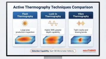
Three active thermography techniques for AM:
- Flash Thermography — A short, high-intensity heat pulse reveals subsurface defects based on heat diffusion. Fast and suited for large-area production inspection
- Lock-In Thermography — A continuous modulated heat source synchronized with infrared measurements. Higher signal-to-noise ratio enables detection at greater depths
- Vibro Thermography — Ultrasound-induced friction heats cracks and delaminations from within, making it particularly effective for tight cracks and kissing bonds that other methods miss
Detection capability: Research demonstrates that active thermography can detect defects smaller than 100 micrometers in AM materials including stainless steel, with depth estimation accuracy within approximately 10% error at defect aspect ratios of 4.
Operational advantages over UT and CT:
- Non-contact — no couplants, no surface preparation required
- No ionizing radiation — no shielding, no radiation safety officers, no specialized facility requirements
- Inspection speeds up to 8–10x faster than contact ultrasound for large-area composite and metal structures
- Operable without formal NDT certification after system training
MoviTHERM's irNDT systems cover all three active thermography techniques and integrate FLIR X-Series scientific cameras — with resolutions up to 1280×1024 and thermal sensitivity down to 20 mK — with application-specific excitation hardware for aerospace, defense, automotive, and composites inspection environments.
NDT Challenges Unique to Additive Manufacturing
Complex Geometries Limit Probe Access
Internal lattices, conformal channels, and thin-wall structures are impossible to reach with contact-based UT probes. That's a fundamental physical constraint — one that pushes AM inspection toward non-contact methods like thermography, resonance testing, and CT. Any NDT plan built exclusively on contact methods will have blind spots in complex AM geometries.
Material Variability Complicates Calibration
AM parts exhibit anisotropic microstructures with properties that shift by build direction. Layer-to-layer thermal gradients introduce residual stress patterns that directly affect NDT signal response. Calibration standards for wrought or cast materials often don't carry over — each material-process combination may need its own qualification dataset.
The Standardization Gap
NIST IR 8538 (2024) confirms that comprehensive AM-specific NDT qualification standards remain under development. The current landscape:
- NASA-STD-6030 (2021) — Requirements for AM of spaceflight hardware
- ASTM E3353 — In-process monitoring for AM (under development)
- ASTM F42 Committee — Ongoing suite of AM material and process standards
The gap means manufacturers must currently bridge missing standards with internal qualification protocols, adding time and cost to AM NDT deployment — particularly in aerospace and medical contexts.
In-Process vs. Post-Process NDT
In-situ monitoring (optical cameras, melt pool sensors, layer-wise thermal imaging) catches defects during the build. Post-process NDT provides final part integrity verification. Neither replaces the other:
- In-process monitoring cannot detect flaws that develop after layer deposition or during post-processing
- Post-process NDT cannot attribute defects to specific build events or catch problems before they compound across subsequent layers
A hybrid strategy combining in-process monitoring with post-build volumetric inspection delivers broader defect coverage than either method alone.
How to Select the Right NDT Method for Your AM Parts
No single method handles every AM inspection scenario. Selection should follow four decision variables:
- Target defect type — Surface-breaking vs. near-surface vs. volumetric
- Material and geometry — Dense metals vs. polymers; simple blocks vs. complex internal channels
- Inspection timing — In-process, immediately post-build, or in-service
- Throughput and cost requirements — High-volume production vs. low-volume critical parts
Method-to-Use-Case Mapping
| Method | Best For | Avoid When |
|---|---|---|
| X-ray CT | Full volumetric characterization of critical parts | High volume, large dense parts, tight cost constraints |
| Ultrasonic (PAUT) | Dense, simpler geometries needing internal flaw depth data | Ka > 15% anisotropy; complex access geometry |
| Resonance Inspection | High-volume pass/fail production triage | Defect localization is required |
| Thermography | Rapid, non-contact inspection of accessible surfaces; composites | Very thick metals; highly reflective surfaces |
| PT / ET | Supplementary surface defect confirmation after finishing | Standalone AM inspection; as-built surfaces |
The Case for Hybrid NDT Strategies
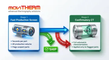
The most effective AM inspection programs don't pick one method — they tier them. A proven approach:
- Resonance inspection or thermography as a fast production screen — Flags suspect parts in seconds without slowing throughput
- CT as a confirmatory tool for flagged parts — Provides full volumetric characterization where it matters most
NIST/LNE collaborative research validates this structure, evaluating resonance acoustic methods and phased array UT as complementary tools rather than competing alternatives.
NDT qualification for AM also requires reference standards — parts with known artificial defects — to validate detection capability. Engaging NDT specialists during the design phase lets inspection requirements shape geometry and material decisions before a single layer is deposited, rather than discovering uninspectable geometries after the build.
How MoviTHERM Can Help
MoviTHERM has specialized exclusively in thermal imaging solutions for industrial monitoring for over 25 years, with customers including Boeing, Airbus, Lockheed Martin, Raytheon Technologies, SpaceX, and NASA. Their irNDT systems cover Flash Thermography, Lock-In Thermography, and Vibro Thermography — each purpose-built for AM part inspection across aerospace, defense, automotive, and composites.
Operational advantages in AM inspection contexts:
- Non-contact operation — no couplants, no surface preparation required
- No ionizing radiation — no shielding, no radiation safety officers, no specialized facility infrastructure
- Inspection speeds 8–10x faster than contact ultrasound (validated by customer experience at Quatro Composites)
- No formal operator certification required — comprehensive training included with every system
Those advantages come from how the systems are built. MoviTHERM integrates FLIR and Optris thermal cameras selected to match specific application requirements, paired with purpose-built excitation hardware and analysis software — delivered as a complete inspection system, not a camera with a manual.
Three branded irNDT products address the most common AM inspection needs:
- C-CheckIR — composite delaminations and bonding defects
- Crack-Check — vibro thermography crack detection in metals and AM structures
- Stress-Check — thermoelastic stress analysis and fatigue characterization
Not sure which approach fits your parts? MoviTHERM offers sample evaluations — send your components, get real results before committing to a system.
Contact MoviTHERM's technical team at +1 (949) 699-6600 or info@movitherm.com to discuss your specific AM inspection requirements.
Frequently Asked Questions
What are the most common non-destructive testing (NDT) methods?
The most widely used methods are X-ray CT, ultrasonic testing, resonance inspection, liquid penetrant testing, eddy current testing, and infrared thermography. Each targets different defect types — CT for internal voids, UT for subsurface cracks, resonance for bulk anomalies, PT/ET for surface defects, and thermography for near-surface and planar features.
What defects are most common in additive manufactured parts?
The primary AM defects are gas porosity, keyhole porosity, lack of fusion between layers, volumetric cracks, trapped powder, and delamination. Most are subsurface and invisible to visual inspection, making NDT essential — particularly in safety-critical applications where a single internal void can initiate fatigue failure.
Can NDT be performed during the additive manufacturing process?
Yes, in-situ monitoring using optical cameras, thermal sensors, and melt pool analysis is possible during the build. It cannot catch flaws that develop during post-processing (heat treatment, HIP, machining), so post-process NDT remains necessary for final part qualification.
What is the best NDT method for inspecting metal 3D-printed parts?
A hybrid approach works best: fast screening methods (thermography or resonance inspection) flag suspect parts, then targeted CT confirms findings. CT offers the most complete internal view but is costly and slow for production-scale volumes. In most cases, this two-stage strategy delivers the best balance of detection confidence and throughput.
How does infrared thermography work as an NDT method for additive manufacturing?
Active thermography applies a brief heat pulse to a part and captures temperature propagation with an infrared camera. Subsurface voids, delaminations, and bonding defects disrupt heat flow and appear as thermal anomalies in the infrared image. This enables non-contact detection with no ionizing radiation, no couplants, and no specialized facility requirements.
What are the biggest challenges of applying NDT to additive manufacturing?
Three challenges stand out:
- Geometry complexity — internal features block physical probe access for contact-based methods
- Missing standards — no comprehensive AM-specific NDT qualification framework exists, so manufacturers build their own protocols
- Anisotropic microstructure — layer-by-layer AM grain structures complicate signal calibration for acoustic methods like UT