The challenge for engineers and safety managers isn't just knowing that thermal runaway exists. It's knowing which signals to watch for, at what thresholds they matter, and which detection tools actually catch problems early enough to act. Surface temperature alone won't cut it. Neither will a BMS alarm that only triggers in Stage IV.
This guide covers all three layers of the problem: what drives thermal runaway internally, how to read the progressive warning signs before failure becomes uncontrollable, and how to configure detection systems that give you a real intervention window.
Key Takeaways
- Thermal runaway follows a predictable five-stage progression; Stages I–III are the critical window for detection and intervention
- Key warning signals include surface temperature anomalies, off-gassing (DMC, EMC, CO, H₂), voltage deviations, and pressure/swelling
- DMC gas sensors can provide up to 15 minutes of warning before onset, far earlier than smoke or temperature-only methods
- Effective detection requires layered monitoring — thermal imaging, gas sensing, and BMS data working together
- NFPA 855 mandates 24/7 continuous monitoring with gas detection at 25% of the Lower Flammable Limit (LFL)
What Causes Thermal Runaway in Lithium-Ion Batteries
The Internal Failure Chain
Thermal runaway begins when heat generation inside a cell outpaces the battery's ability to dissipate it. Three abuse categories trigger this:
- Thermal abuse — external heat exposure or inadequate cooling
- Electrical abuse — overcharging, over-discharging, or charging at rates beyond the rated C-rate
- Mechanical abuse — puncture, crush, or impact damage causing internal short circuits
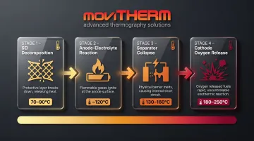
Once initiated, the failure chain follows a predictable sequence:
- SEI decomposition at 70–90°C — the solid electrolyte interphase breaks down, exposing the anode directly to the electrolyte
- Anode-electrolyte reaction at ~120°C — intercalated lithium reacts exothermically
- Separator collapse at 130–160°C — internal short circuits begin
- Cathode oxygen release at 180–250°C — self-sustaining exothermic cycle begins, driving temperatures above 600°C
Fast charging introduces additional risk. Lithium plating from high charge rates can drop the self-heating onset temperature to as low as 60°C — well below normal abuse thresholds.
SOC, Aging, and Chemistry
Those mechanical triggers don't operate in isolation — state of charge and cell chemistry determine how severe the outcome becomes. Research published in Processes confirms that thermal runaway severity increases when SOC exceeds 50%. At 100% SOC, energy released during runaway can approach 1–1.5x the energy supplied during charging.
Battery chemistry is also a front-line safety variable:
| Chemistry | Thermal Runaway Onset | Risk Profile |
|---|---|---|
| LCO (Lithium Cobalt Oxide) | ~140–160°C | Highest risk; oxygen release at lower temperatures |
| NMC (Nickel Manganese Cobalt) | ~206°C (pouch cell) | High risk; peak heating rate orders of magnitude above LFP |
| LFP (Lithium Iron Phosphate) | ~244°C (pouch cell) | Most stable; phosphate bond resists oxygen release |
Aging elevates risk across all chemistries by increasing internal resistance and reducing thermal margins. Of 35 documented US BESS fire incidents between 2012 and 2024, 44% occurred within the first six months of operation — which means continuous monitoring during commissioning isn't optional; it's where the risk is highest.
Warning Signs: How to Know If a Battery Is Approaching Thermal Runaway
Understanding the five-stage progression is what separates effective detection from reactive damage control. Stages I–III are where intervention is still possible. By Stage IV, options narrow quickly.
Stage I – Early Thermal Expansion
Surface temperature begins rising into the 30–90°C range. Slight strain or swelling may be detectable. No electrical anomalies appear yet.
This is the optimal detection window — but only if you have continuous thermal monitoring in place. A once-daily inspection won't catch it.
Stage II – Electrolyte Venting and Gas Generation
The SEI membrane begins decomposing. The cell starts to swell. Early off-gassing of DMC and EMC begins — and these electrolyte vapors are detectable well before hydrogen or CO appear.
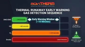
According to Zhang et al., DMC becomes detectable at approximately 390 seconds, while H₂ doesn't appear until 1,312 seconds. That's nearly 16 minutes of additional warning time if you're monitoring for the right gases.
Key gas detection sequence at Stage II:
- DMC/EMC vapors — first detectable around 390 seconds; primary early-warning indicator
- H₂ and CO — appear ~1,312 seconds in; confirmation of accelerating decomposition
Stage III – Separator Stress and Accelerating Gas Production
Internal gas pressure builds. Mechanical strain accelerates. Temperature may plateau temporarily as the separator absorbs heat.
Critical point: Voltage may still appear normal at this stage. This is exactly why relying solely on BMS voltage monitoring is insufficient — gas and thermal signals are the only reliable indicators here.
Stage IV – Rapid Temperature Surge
Temperature rate-of-rise exceeds 10°C/min (0.17°C/s), approaching the transition to uncontrollable runaway. Anode decomposition accelerates. CO, CO₂, and H₂ emissions increase substantially. BMS alarms may trigger here — but intervention options are already limited.
Stage V – Full Thermal Runaway
Rate-of-rise exceeds 1°C/s: the threshold for catastrophic, uncontrollable thermal runaway identified in published literature. Venting, smoke, and ignition are likely. In battery packs, adjacent cells are now at risk of cascade failure.
Stages I–III are where continuous gas and thermal monitoring make the difference. By the time Stage IV begins, the question is no longer whether to act — it's whether your team was already notified in time to do so.

Detection Methods: Tools and Techniques for Early Warning
No single detection method covers all stages. Effective monitoring requires at least two complementary methods running simultaneously.
Method 1: Infrared Thermal Imaging
What it detects: Continuous surface temperature mapping across battery packs, identifying localized hot spots before they propagate. Effective from Stage I onward.
How to deploy:
- Mount fixed radiometric cameras with full field of view of the battery pack — pan-tilt units can extend coverage across larger rack arrays
- Configure temperature alarm thresholds relative to ambient baseline and battery chemistry
- Integrate with a monitoring platform for continuous logging and alert escalation
- Set multi-level alert thresholds: warning for trend deviations, critical for rate-of-rise events
Camera specifications to look for:
| Parameter | Target Range |
|---|---|
| Thermal sensitivity (NETD) | <50 mK (ideally <30 mK) |
| Resolution | 320×240 minimum; 640×480 for larger arrays |
| Temperature range | -20°C to 120°C minimum |
| Accuracy | ±2°C or ±2% of reading |
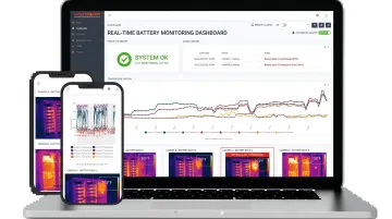
Recommended system: MoviTHERM's FLIR A400/A500/A700 series cameras meet these specifications for 24/7 continuous monitoring. Paired with the iTL cloud monitoring platform, they deliver automated text, voice, and email alerts plus remote dashboard access from any internet-connected device. The iTL Gateway also maintains local alarm functionality if network connectivity drops — a practical safeguard in industrial environments.
Limitations: Surface temperature lags internal temperature by an average of 5.8°C, with internal events detectable up to 10x faster than surface readings. Thermal cameras require clear line of sight and cannot penetrate enclosure walls.
Method 2: Gas Sensor Detection
Gas sensors detect off-gas composition inside battery enclosures. DMC and EMC appear in Stage II — well before CO, H₂, or smoke — making them among the earliest chemical indicators available.
Sensor placement by gas type:
- H₂ is lighter than air — sensors must be mounted at the ceiling or highest point of the enclosure
- DMC/EMC vapors are heavier than air — sensors should be placed within 6–12 inches of the floor
- Placing H₂ sensors at floor level (a common mistake) will significantly delay detection
Gas thresholds by stage:
| Gas | Detection Timing | Relevance |
|---|---|---|
| DMC/EMC | ~390 seconds (earliest) | Stage II indicator; 15-min advance warning possible |
| CO | ~482 seconds | Stage III–IV indicator |
| H₂ | ~1,312 seconds | Late-stage; 639 seconds faster than smoke detection |
NFPA 855 requires gas detection systems to alarm at 25% of the Lower Flammable Limit (LFL) for lithium-ion BESS installations, with signals transmitted to a continuously attended location.
Limitations: Gas sensors cannot pinpoint the specific cell generating the off-gas and are subject to calibration drift and ambient contamination — pair with thermal imaging for cell-level localization.
Method 3: BMS Electrical Parameter Monitoring
BMS monitoring tracks per-cell voltage deviations, temperature rate-of-rise, capacity fade, and current anomalies. It's most useful for catching overcharge and over-rate conditions before they escalate.
Key thresholds to configure:
- 1°C/min — onset of self-heating; initial warning threshold
- 10°C/min (~0.17°C/s) — transition toward rapid thermal runaway
- 1°C/s — catastrophic, uncontrollable thermal runaway
Deployment steps:
- Configure BMS for high-frequency per-cell voltage and temperature logging
- Establish baseline profiles for each battery pack under normal operating conditions
- Set alerts for voltage dip/spike, temperature rate-of-rise, and capacity deviation
- Review historical trends regularly — progressive degradation patterns often precede acute events
Limitations: Voltage anomalies typically appear only in Stage IV–V, and surface temperature sensors lag internal readings significantly. BMS monitoring alone is not sufficient for early warning — it must be paired with gas or thermal detection.
How to Interpret Detection Signals and When to Act
Each detection signal maps to a specific response tier. The three states below define what normal, early warning, and imminent runaway look like — and exactly what to do at each stage.
Normal Baseline State
- Surface temperatures stable and uniform across all cells and modules
- No gas concentrations above ambient background
- Voltage curves following expected charge/discharge profiles
- No visible swelling or mechanical deformation
Action: Continue routine monitoring. Document this baseline — it becomes your comparison reference for every future deviation.
Warning: Early Deviation (Stages I–III)
- Localized temperature rise of 5–15°C above neighboring cells or modules
- DMC or EMC detected above background threshold
- Slight voltage deviation or early capacity fade
Action: Increase monitoring frequency. Reduce charge rate. Isolate the affected module if possible. Alert maintenance personnel and begin an incident log. Do not wait for a BMS alarm to confirm what gas and thermal sensors are already showing.
Critical: Imminent Runaway (Stages IV–V)
- Temperature rate-of-rise approaching or exceeding 10°C/min
- H₂ and CO present alongside DMC/EMC
- Voltage collapse or sharp spike
- Visible swelling, audible venting, or smoke
Action: Immediate system shutdown. Evacuate per emergency protocol. Alert emergency services. Do not attempt water suppression without first consulting your fire response plan. NFPA guidance permits water on lithium-ion fires — unlike metallic lithium, the lithium here is not in free form — but verify this applies to your specific installation. Monitor temperature until the system returns to ambient under fire service supervision.
Safety Practices and Prevention Measures
Establish 24/7 Continuous Monitoring
Thermal runaway doesn't follow business hours. Of 35 documented US BESS fires between 2012 and 2024, 69% occurred during active system use — including charging and standby states. Any battery system above a minimal threshold needs always-on monitoring with automated alerting.
The iTL platform from MoviTHERM supports this directly: gateway-level alarm triggering operates independently of cloud connectivity, meaning alerts fire even during network outages — a critical detail for remote or grid-edge installations.
Implement Charge Management Best Practices
- Keep daily charge cycles between 20–80% SOC — onset temperatures drop measurably above 50% SOC, increasing runaway risk
- Never charge above the battery's rated upper cutoff voltage
- Avoid sustained high-rate charging beyond the rated C-rate, which risks lithium plating and sharply reduces onset temperatures
- For long-term idle storage, target 40–60% SOC
Define and Rehearse Emergency Response Protocols
Personnel should not improvise when a Stage III or Stage IV signal appears. Define and rehearse:
- Isolation procedures — which modules to disconnect and in what order
- Lockout/tagout requirements — preventing re-energization during incident response
- PPE requirements — face shield, thermal-resistant gloves at minimum
- Evacuation routes — confirmed clear, not assumed
- Emergency contact chain — who gets called, in what order, with what information
Run tabletop drills at least twice a year — and a live walkthrough before any system expansion or personnel changeover.
Frequently Asked Questions
What is thermal runaway detection?
Thermal runaway detection refers to monitoring systems and sensors that identify the physical, chemical, and electrical signals preceding a self-sustaining exothermic chain reaction in a battery cell. The goal is to detect early enough — ideally in Stages I–III — that operators can intervene before catastrophic failure.
What causes thermal runaway in batteries?
Three abuse categories initiate it: thermal (overheating from external sources or poor cooling), electrical (overcharging, over-discharging, or high charge rates), and mechanical (puncture, crush, or impact). Internal short circuits and battery aging elevate risk across all categories.
How do you know if a battery is in thermal runaway?
Key observable indicators include rapid surface temperature rise, swelling or bulging, audible venting sounds or gas odor, smoke, and BMS alarms for voltage or temperature deviation. By the time these signs appear visually, the reaction is typically already in Stage IV or V, which is why continuous automated monitoring is essential.
What is the early warning system for thermal runaway in an ESS?
Effective ESS early warning systems combine continuous fixed thermal imaging, multi-gas sensors targeting DMC/EMC before hydrogen appears, and BMS-based electrical monitoring. This layered approach covers all stages of progression, with gas sensors offering the longest lead time — up to 15 minutes before onset.
How do you prevent thermal runaway in batteries?
Core prevention measures include:
- Stay within rated charge parameters (no overcharging, no excessive C-rate)
- Keep SOC in the 20–80% range for normal operation
- Conduct 24/7 thermal and gas monitoring
- Inspect regularly for mechanical damage
- Operate within the manufacturer's temperature range
Which battery chemistries are most prone to thermal runaway?
NMC and LCO chemistries carry the highest risk due to cathode oxygen release at elevated temperatures. NMC reaches thermal runaway onset at approximately 206°C versus LFP's 244°C, with peak heating rates an order of magnitude higher. LFP's olivine structure doesn't release oxygen under typical abuse conditions, making it considerably more stable — though no lithium-ion chemistry is immune, and higher SOC increases risk across all of them.