Introduction
Switchgear is the backbone of industrial and commercial power distribution — and overheating is one of its most persistent threats. Loose bolts, oxidized contacts, and worn components generate resistance that accumulates quietly until a connection fails, an arc flash occurs, or an unplanned outage forces an emergency shutdown.
According to ESFI data, there were 5,180 nonfatal electrical injuries in 2023–2024 — a 59% increase from 2021–2022 — with utilities recording the highest electrical fatality rate of any sector. Many of those incidents trace back to thermal faults that went undetected.
This guide breaks down what switchgear thermal monitoring is, how the main approaches compare, and what it takes to build a program that keeps equipment running and people safe.
Key Takeaways
- Thermal monitoring detects dangerous heat buildup at busbars, breaker contacts, and cable terminations before faults escalate
- Undetected overheating drives arc flash events, insulation breakdown, and unplanned outages in switchgear
- Four monitoring approaches: periodic IR thermography, continuous fixed cameras, wireless sensors, and fiber optic sensing
- Early warning signs include phase temperature differentials, nuisance tripping, visible heat discoloration, and repeating faults at the same component
- Structured programs with defined intervals, alarm thresholds, and trend review are required for NFPA 70B compliance and predictive maintenance
Why Switchgear Thermal Monitoring Is Essential
Switchgear components carry high currents continuously. Even a minor resistance increase (from a loose bolt, corroded lug, or worn contact) generates heat that compounds over time. Left unchecked, this leads to insulation degradation, contact failure, and in the worst cases, thermal runaway and arc flash.
The safety stakes are concrete. NFPA's 2023 data recorded 142 occupational fatalities from electrical exposure and 5 from electric arcs in a single year. OSHA notes that most arc flash burn injuries occur not from the arc itself, but from ignited clothing — meaning the window for intervention matters.
Compliance Drivers
Thermal monitoring is increasingly tied to mandatory maintenance standards:
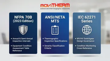
- NFPA 70B (2023 Edition) — Transitioned from a recommended practice to a standard. It prescribes infrared thermographic inspection at least annually for normal-condition equipment and semi-annually for Condition 3 equipment, with intervals set by an Equipment Condition Assessment using Table 9.2.2
- ANSI/NETA MTS — Includes thermographic inspection within its maintenance testing specifications and provides severity classification criteria for temperature anomalies
- IEC 62271 series — Governs MV/HV switchgear design and is cross-referenced in condition monitoring literature
The Cost Comparison
DOE predictive maintenance research puts maintenance cost reductions at 25–30% for facilities running predictive programs, with larger savings once unplanned outage costs enter the calculation. A single catastrophic switchgear failure — emergency replacement, extended production shutdown, injury liability, and regulatory scrutiny — can cost more than years of continuous monitoring combined.
Types of Switchgear Thermal Monitoring
No single approach fits every application. Voltage level, accessibility, enclosure design, and whether you need periodic or continuous coverage all shape the right choice.
Periodic IR Thermography
Handheld thermographic inspections use a qualified thermographer with an infrared camera — typically through IR windows or during a planned open-panel inspection — to scan connection points and flag temperature differentials.
Strengths:
- Low upfront cost and no permanent installation required
- Provides a documented baseline thermal record
Limitations:
- Snapshot only — faults developing between annual or semi-annual visits go undetected
- Requires qualified personnel, appropriate PPE, and line-of-sight access to energized components
- Labor-intensive and subject to scheduling gaps
For most facilities, periodic thermography serves as a starting point. On its own, it's rarely sufficient for critical assets.
Continuous Fixed Thermal Monitoring
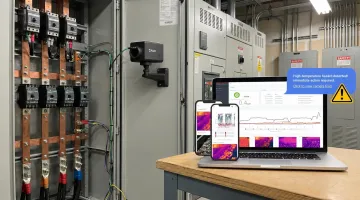
Permanently mounted infrared sensors or cameras provide 24/7 coverage of critical connection points. Real-time data flows to a monitoring system or cloud platform, with configurable alarm thresholds that trigger immediate alerts when temperatures breach defined levels.
This is MoviTHERM's core offering for switchgear applications. A complete system typically includes:
- Fixed FLIR A-Series cameras (A50 or A70, up to 640×480 pixels, thermal sensitivity under 35 mK)
- IP66/67-rated enclosures for harsh industrial environments
- Intelligent I/O Module (MIO) for analog and digital output integration
- iTL cloud monitoring platform with alerts via text, email, and voice call, plus customizable dashboards accessible from any device
The MIO connects to cameras via Modbus TCP/IP, evaluates temperature readings several times per second, and outputs 4–20mA signals directly to SCADA or PLC systems. The iTL Gateway also supports Ethernet/IP, MQTT with TLS, and HTTP/HTTPS for broader integration flexibility.
Continuous monitoring eliminates the inspection gap that periodic thermography leaves — and reduces thermal assessment time by up to 10x compared to manual survey methods.
Wireless Temperature Sensors
Battery-powered or energy-harvesting wireless sensors attach directly to busbars, contacts, or cable lugs and transmit temperature data to a nearby gateway. They're popular for retrofitting existing switchgear without extensive cable runs.
Trade-offs to consider:
- Lower upfront cost and simpler installation
- Metal switchgear enclosures attenuate RF signals, complicating link budgets and potentially causing data gaps
- Battery life and sensor health require ongoing management
- Passive SAW (surface acoustic wave) sensors address the battery constraint but face the same RF attenuation issue
Wireless sensors work best as a complement to other approaches, particularly in lower-criticality locations where continuous wired monitoring isn't justified. Where electromagnetic interference is the primary constraint — rather than cable routing — fiber optic sensing is worth evaluating instead.
Fiber Optic Temperature Sensing
Fiber optic sensors — FBG (Fiber Bragg Grating), fluorescence-based, or distributed temperature sensing — are the preferred solution for MV and HV switchgear where electromagnetic interference makes metal-based sensors impractical.
| Method | EMI Immunity | Direct Contact with HV Parts | Best Use Case |
|---|---|---|---|
| FBG | High | Yes (with proper mounting) | HV switchgear, multiplexed sensing |
| Fluorescence-based | High | Yes (with proper mounting) | High-precision point measurement |
| Distributed (DTS) | High | Fiber routed near conductors | Long-run thermal mapping |
Because optical fibers are inherently non-conductive, they can be placed in contact with energized high-voltage components safely. These systems last the lifetime of the switchgear — typically 30+ years — with minimal maintenance requirements.

Warning Signs That Your Switchgear Needs Thermal Monitoring Attention
These signals apply whether a facility has a monitoring system in place or relies on periodic inspections.
Abnormal Temperature Differentials Between Phases
A significant temperature difference between phases at the same connection type is one of the most reliable early indicators of a developing fault. Phase comparison is more informative than absolute temperature alone. A connection running at 60°C isn't necessarily a problem — but if the adjacent phase is at 40°C under identical load conditions, that 20°C differential warrants investigation.
ANSI/NETA MTS provides severity classification criteria for these anomalies, giving maintenance teams a clear framework for prioritizing corrective action.
Unexpected Tripping or Circuit Breaker Operation
Thermal stress from loose or degraded connections can cause overcurrent protective devices to operate prematurely. Nuisance trips and intermittent faults often precede a more serious failure. If a breaker is resetting repeatedly with no apparent load explanation, a developing thermal fault at the connection is the most probable cause.
Physical Indicators of Heat Damage
The following indicators are the most urgent — excessive heat has already occurred, and re-energizing without inspection is not an option:
- Discoloration or charring on busbars or surrounding insulation
- Deformed or melted components near connection points
- Burning smell in the switchgear room
- Heat staining on panel surfaces or cable insulation near terminations
Any of these findings warrants immediate inspection before re-energizing.
Rising Thermal Trend Data Over Time
Continuous monitoring provides something periodic inspections cannot: a baseline to measure against. When temperatures at a specific point climb steadily over weeks or months — even below alarm thresholds and under stable load conditions — that upward trend is a stronger predictor of an emerging fault than any single reading. It turns thermal monitoring from reactive detection into genuine prediction.
Repeated Maintenance at the Same Component
If a maintenance team keeps retightening the same connection, resetting the same breaker, or replacing the same fuse, that pattern points to an unresolved underlying issue. The component may be thermally stressed to the point where temporary fixes no longer hold.
Building a Switchgear Thermal Monitoring Program
Choosing a sensor is the starting point. What separates a functioning program from a reactive one is everything that comes after: where you monitor, how often, what triggers action, and who responds.
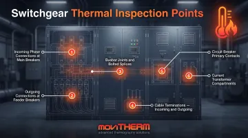
Define Critical Monitoring Points
Every switchgear lineup should include these locations as a minimum:
- Incoming phase connections at main breakers
- Outgoing connections at feeder breakers
- Busbar joints and bolted splices
- Cable terminations (both incoming and outgoing)
- Circuit breaker primary contacts
- Current transformer compartments
Higher-load or higher-criticality points warrant priority — particularly in facilities where an outage at a specific feed would stop a production line or impact life safety systems.
Establish Monitoring Frequency
| Equipment Type | Monitoring Approach | Recommended Frequency |
|---|---|---|
| Continuous monitoring systems | Fixed sensors/cameras | Real-time, 24/7 with configurable thresholds |
| High-criticality assets (data centers, primary distribution) | Periodic thermography | Every 6 months, supplementing continuous |
| Standard industrial assets | Periodic thermography | Annually, or more often after faults/load changes |
| New installations or post-maintenance | Baseline thermal scan | Within first weeks of operation |
NFPA 70B 2023 codifies the condition-based approach: normal equipment inspected annually, Condition 3 equipment semi-annually, with intervals formally set through an Equipment Condition Assessment.
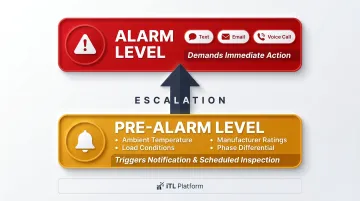
Set Alarm Thresholds and Response Protocols
Fixed absolute thresholds alone are insufficient. Effective alarm configuration accounts for:
- Ambient temperature at time of measurement
- Load conditions (a connection running at 80% capacity will read warmer than one at 40%)
- Equipment manufacturer temperature ratings
- Phase-to-phase differential comparison
A tiered approach works well in practice: a pre-alarm level triggers notification and scheduled inspection, while an alarm level demands immediate action. The iTL platform supports both, with customizable alert routing via text, email, or voice call. Alarm responses execute locally at the gateway the moment a threshold is breached — independent of cloud update rates.
Document the corrective action procedure for each alarm tier. A pre-alarm without a defined owner and response path is an unfinished program.
Integrate Data with Maintenance and Operations Systems
The iTL Gateway supports Modbus/TCP, MQTT, and Ethernet/IP — connecting directly to SCADA systems, PLCs, and CMMS platforms. The MIO module's 4–20mA analog outputs feed into existing plant monitoring infrastructure without added middleware.
This integration enables automatic work order generation when alarm conditions occur, trend-based maintenance scheduling, and audit trails for compliance and insurance reporting.
Document and Review Findings Regularly
Raw data without periodic review tells you nothing useful. Schedule monthly or quarterly reviews to:
- Assess temperature trends against established baselines
- Update baselines as load conditions change seasonally or operationally
- Adjust alarm thresholds where trending data suggests they're set too conservatively or too aggressively
- Document all findings with timestamps for insurance, compliance, and asset management records
The iTL platform supports scheduled reports delivered daily, weekly, or monthly to designated email recipients — making this review process easier to sustain consistently.
Conclusion
Switchgear thermal monitoring is an ongoing program, not a periodic task. The cost of a structured monitoring approach — cameras, sensors, platform subscriptions, and inspection labor — is consistently less than the cost of a single unplanned outage, let alone an arc flash incident.
The right program balances monitoring method against criticality: continuous fixed monitoring for primary distribution and high-consequence assets, while scheduling periodic thermographic inspections for lower-priority assets. Even facilities starting with annual IR surveys should have a defined path to continuous monitoring for their most critical switchgear.
A well-executed thermal monitoring program delivers on three fronts:
- Personnel safety — early detection of arc flash precursors before conditions escalate
- Asset reliability — predictive maintenance that prevents unplanned failures
- Compliance documentation — audit-ready records for NFPA 70B and ANSI/NETA MTS requirements
Fixed-mount thermal cameras paired with a continuous monitoring platform give facilities all three simultaneously, around the clock.
Frequently Asked Questions
What is switchgear monitoring?
Switchgear monitoring is the systematic measurement of key operating parameters — particularly temperature — at critical points within LV, MV, or HV switchgear assemblies. The goal is detecting abnormal conditions such as overheating at connections, phase imbalances, or degraded contacts before they escalate into failures or safety incidents.
What is a SCADA temperature monitoring system?
SCADA (Supervisory Control and Data Acquisition) temperature monitoring collects real-time data from sensors across switchgear, displays trends and alarms on a central platform, and enables remote control. Data flows through RTU/edge gateways into SCADA or CMMS systems, integrating thermal monitoring into broader facility operations.
What are the four types of temperature sensors used in switchgear?
The four common types are thermocouples, resistance temperature detectors (RTDs), infrared (IR) sensors, and fiber optic sensors. In high-voltage switchgear, IR and fiber optic are preferred — IR for non-contact measurement, fiber optic where strong EMI requires non-conductive sensing.
How often should switchgear thermal inspections be performed?
NFPA 70B 2023 specifies at least annual thermographic inspection for normal-condition equipment and semi-annual for Condition 3 equipment, with intervals set through an Equipment Condition Assessment. Continuous monitoring systems eliminate the gap between scheduled inspections entirely, providing real-time detection around the clock.
What are the most critical points to monitor in switchgear?
The highest-priority locations are busbar joints and bolted connections, circuit breaker primary contacts, incoming and outgoing cable terminations, and current transformer compartments. These points carry the highest currents and are most susceptible to resistance increases from connection degradation.
Can thermal monitoring prevent arc flash incidents?
Thermal monitoring doesn't directly prevent arc flash, but it detects the overheating conditions — loose connections, excessive resistance, overloaded components — that are recognized precursors. Catching and correcting these issues early gives maintenance teams a window to intervene before a failure occurs.