Introduction
Industrial electrical failures don't announce themselves—they develop silently over weeks or months, slowly increasing resistance at connections, building friction in bearings, and creating hot spots that eventually trigger catastrophic failures. In U.S. manufacturing alone, unplanned downtime costs up to $207 million weekly, with 83% of decision-makers reporting costs of at least $10,000 per hour.
The financial toll is only part of the story. Between 2017 and 2021, industrial and manufacturing properties experienced 36,784 fires annually, resulting in $1.5 billion in direct property damage, 22 civilian deaths, and 211 injuries.
Electrical distribution and power transfer equipment alone accounted for 21% of those fires and 29% of property damage, with arcing as the leading heat source.
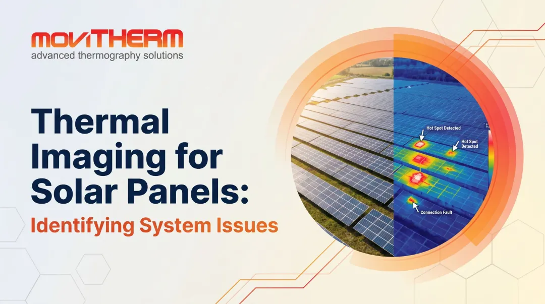
Thermal imaging hot spot detection catches these anomalies before they escalate. This guide explains how thermal cameras detect hot spots, the three main inspection methods, how to interpret findings correctly, and where common mistakes lead to missed or false detections.
Key Takeaways
- Hot spots signal faults like increased electrical resistance, mechanical friction, or insulation breakdown; thermal cameras catch them without contact or system shutdowns
- Inspection approach depends on your application: periodic handheld scans for accessible equipment, fixed cameras for continuous monitoring, or cloud-based platforms for remote 24/7 coverage
- Equipment must run above 40% load capacity during inspection, and emissivity settings must match surface materials to avoid missed detections or false readings
- Classify severity using temperature differentials (not absolute temps); the delta drives your response: watch, schedule, or act immediately
What You Need to Detect Hot Spots with Thermal Imaging
Successful hot spot detection comes down to three things: the right camera, the right conditions, and a system to act on what you find. Here's what each requires.
Tools and Equipment Required
Core equipment includes:
- Thermal infrared camera with resolution and temperature range matched to your specific assets — fixed-mount cameras are standard for continuous industrial monitoring
- Emissivity reference materials or tape to correct emissivity on metallic and coated surfaces, where inaccurate settings produce misleading temperature readings
- Reference thermometer for spot-checking camera accuracy
- Software for image capture and analysis to document findings and track trends over time
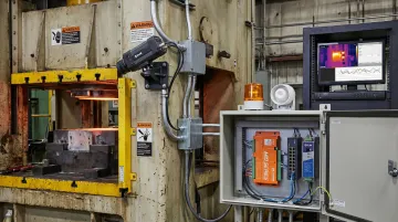
For industrial monitoring applications, MoviTHERM supplies complete fixed-camera systems — including FLIR A-Series, Optris PI/Xi Series, and Seek cameras — paired with mounting hardware, I/O modules, and integration support tailored to your facility's requirements.
Preconditions and Setup
Load conditions matter: Assets must operate at or near normal load — at least 40% capacity for electrical systems per NETA thermographic inspection standards. Hot spots caused by resistance often disappear at low load, creating false confidence that equipment is healthy when it's not.
Access and safety considerations: For enclosed electrical panels, IR windows allow thermal inspection without opening energized equipment, significantly reducing arc flash risk. For outdoor or hard-to-reach assets, fixed cameras eliminate access barriers entirely while providing continuous coverage.
How Thermal Imaging Identifies Hot Spots
Thermal cameras detect infrared radiation emitted by objects and convert it into a temperature map. All objects above absolute zero emit IR in the long-wave infrared atmospheric window of 7.5–14 µm. Faults that increase resistance, friction, or block heat dissipation cause localized temperature rises visible as bright areas in the thermal image.
Emissivity: The Complicating Factor
Emissivity—a material's efficiency at emitting thermal radiation—complicates accurate readings for industrial assets. Highly polished metallic surfaces such as copper or aluminum typically have emissivity below 0.10, meaning the camera significantly underestimates their actual temperature. Meanwhile, most organic, painted, or oxidized surfaces have emissivity close to 0.95.
Practical solutions:
- Apply high-emissivity electrical tape or paint to create a measurable surface
- Adjust emissivity value in camera settings based on known material properties
- Never make quantitative decisions on surfaces below 0.60 emissivity—reflected radiation from surrounding heat sources will dominate the reading
Skip emissivity correction and you risk missing real faults on bare metal—or chasing false alarms that trigger unnecessary shutdowns.
Identifying True Electrical Hot Spots
The thermal pattern reveals the difference between a genuine fault and background heating. A true electrical hot spot shows heat concentrated at the fault point—such as a loose connection or corroded contact—with temperature trailing away as it conducts outward. This "source and gradient" pattern distinguishes resistance-based faults from uniform background heating.
Once you recognize the pattern, the next question is: what's causing it? That depends on the asset type.
Main Industrial Causes of Hot Spots
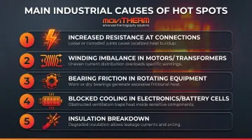
Thermal imaging detects:
- Increased resistance at electrical connections: loose, corroded, or undersized contacts. Industry data suggests 25% of electrical failures stem from faulty connections, with some claim sets showing 80% of incidents from connection failures
- **Winding imbalance in motors and transformers**—uneven heating indicates developing insulation breakdown or phase imbalance
- **Bearing friction in rotating equipment**: elevated temperatures at bearing housings signal lubrication failure or misalignment
- Blocked cooling in electronics or battery cells—localized hot spots in battery banks can precede thermal runaway
- Insulation breakdown: deteriorating insulation creates current leakage paths that generate heat
Qualitative vs. Quantitative Inspection
| Method | How It Works | Best Used For |
|---|---|---|
| Qualitative | Compares similar components under identical load (e.g., same phase, same equipment type) | Electrical systems where emissivity varies; if phase A runs 15°C hotter than phases B and C, you have a fault—regardless of absolute temperature |
| Quantitative | Measures absolute temperature; requires known, stable emissivity | Painted surfaces, composite materials, battery monitoring, electronics cooling verification where direct pass/fail thresholds apply |
Methods to Detect Hot Spots Using Thermal Imaging
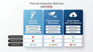
Three main approaches exist: periodic handheld inspection, fixed automated monitoring, and continuous cloud-based surveillance. Each suits different asset criticality, access requirements, and inspection frequency needs.
Method 1: Periodic Handheld Thermal Inspection
A technician carries a portable thermal camera and scans equipment during scheduled inspection routes: panels, motors, cable trays, junction boxes, and transformers.
Step-by-Step:
- Confirm asset is at normal operating load (minimum 40% capacity for electrical)
- Adjust emissivity setting on camera for surface material
- Scan across components systematically, pausing to capture and annotate thermal images of anomalies
- Compare findings against baseline images from prior inspections
Pros:
- Cost-effective for infrequent inspections
- Best for accessible equipment
- Lower upfront investment than fixed systems
Cons:
- Limited to snapshot-in-time coverage—intermittent faults between inspection cycles are missed
- Exposes technicians to proximity with energized equipment
- Requires consistent load conditions to catch developing problems
Method 2: Fixed Camera Automated Monitoring
Where handheld inspection leaves gaps between rounds, fixed cameras close them. Permanently mounted to monitor critical assets such as switchgear, battery banks, conveyor bearings, and production lines, these systems trigger alerts automatically when temperatures exceed software-defined thresholds.
Step-by-Step:
- Mount camera at correct distance and angle to achieve full coverage of target
- Configure regions of interest (ROIs) in monitoring software with alarm thresholds based on baseline temperatures
- Connect to site alarm or notification system for automatic alerts
Pros:
- Continuous coverage catches developing faults between inspection rounds
- Removes need for technician access to live equipment
- Documents thermal trends over time for predictive maintenance decisions
Cons:
- Higher upfront investment than handheld
- Requires careful installation planning for optimal coverage
- Fixed field of view limits flexibility for future equipment changes
Method 3: Continuous Cloud-Based 24/7 Thermal Surveillance
Fixed cameras feed thermal data to a cloud monitoring platform that stores trend data and enables remote access from any location. Automated alerts via text, voice, and email fire when hot spots exceed defined thresholds, with no on-site staff required.
Step-by-Step:
- Deploy fixed thermal cameras integrated with cloud monitoring system
- Configure alert thresholds and notification recipients
- Monitor trend data remotely over time to distinguish developing faults from normal thermal variation
- Review archived images to support maintenance scheduling
Pros:
- Suited for critical assets, remote sites, and facilities requiring 24/7 coverage
- Enables predictive maintenance decisions based on trend data rather than single-point readings
- Provides documented thermal history for root cause analysis after failures
Cons:
- Highest initial cost of all three approaches
- Requires reliable network connectivity
- May require IT security review for cloud data transmission
MoviTHERM's iTL platform follows this model: fixed cameras integrated with cloud monitoring, trend archiving, and multi-channel alerting. For facilities managing remote sites or assets where unplanned downtime is not an option, this approach shifts thermal monitoring from a periodic inspection task to an always-on risk management layer.
How to Interpret Thermal Hot Spot Readings
A raw temperature number alone tells you little. Context determines whether a hot spot needs immediate action or routine monitoring. Miss a real fault and you risk equipment failure; flag a false positive and you trigger an unnecessary shutdown. Both outcomes cost time and money.
Normal/Acceptable Readings
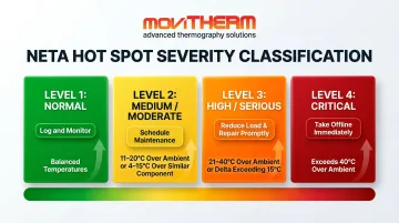
Balanced temperature across similar components under similar load, with minor heat gradients consistent with current-carrying conductors operating within design limits.
Log the baseline reading and continue scheduled monitoring.
Moderate Concern
NETA thermographic standards classify Level 2 (Medium) severity as 11–20°C over ambient or 4–15°C over a similar component. This range indicates phase asymmetry or a localized warm point consistent with early-stage resistance buildup.
Flag for scheduled maintenance and increase inspection frequency. The fault is developing, not yet critical.
Serious/Immediate Action
NETA Level 3 (High) runs 21–40°C over ambient with a delta exceeding 15°C versus a similar component; Level 4 (Critical) exceeds 40°C over ambient. A clear thermal gradient radiating from a single point signals high risk of failure or fire.
Reduce or redistribute load and schedule immediate repair. If the signature continues to worsen, take the asset offline.
False Positive Indicators
Three conditions routinely produce misleading readings:
- Reflected radiation: Low-emissivity metals act like mirrors, displaying heat from nearby sources rather than the surface itself. If the hot spot shifts when you change viewing angle, it's a reflection — not a fault.
- Solar loading: Direct sunlight heats outdoor enclosure surfaces well above internal temperatures. Schedule outdoor inspections during cooler periods or after sunset.
- Uncorrected emissivity: Bare copper or aluminum bus bars without emissivity correction often show reflected heat, not genuine resistance. Apply high-emissivity tape to the spot and re-scan to confirm.
Common Errors and Best Practices for Thermal Hot Spot Inspections
Inspecting Under the Wrong Conditions
The most common missed detection cause: scanning electrical equipment at low load—under 40% capacity—means resistance-based hot spots generate insufficient heat to stand out. NETA standards explicitly require conducting scans under maximum practicable load but not less than 40% of nominal.
Before starting any scan:
- Confirm load is at or above 40% of nominal capacity
- Reschedule if load conditions can't be met
- Document the load level in your report — "no hot spot detected" means nothing if conditions weren't verified
Incorrect Emissivity Setting
Polished metal components reflect IR energy from surrounding sources, causing the camera to read inflated or deflated temperatures. If a target's emissivity is below 0.50, you are unlikely to get an accurate temperature measurement without correction.
Apply high-emissivity tape to the target surface, or adjust the emissivity value in camera settings based on known material values. For surfaces below emissivity 0.60, skip absolute temperature readings entirely — comparative analysis is the safer approach for any quantitative decisions.
Single-Component Focus Without Comparison
Flagging a component as a hot spot without comparing it to identical components under identical load leads to false positives. A terminal reading 85°C might seem concerning in isolation but is normal if all three phases read similarly.
Always compare phase-to-phase, unit-to-unit, or against a previously established baseline. Relative differences expose real anomalies far more reliably than absolute temperatures for electrically complex equipment.
Taken together, these three errors — wrong load, wrong emissivity, wrong reference — account for the majority of missed or misclassified hot spots in the field. Getting each one right is a repeatable process, not guesswork.
Frequently Asked Questions
What is hotspot detection?
Hot spot detection is the process of identifying areas of abnormally elevated temperature in equipment or systems using thermal imaging cameras. It reveals developing faults such as increased electrical resistance, friction, or heat buildup before they cause failure.
What is a hotspot sensor?
A hotspot sensor is a fixed infrared camera or thermal detector configured to monitor a specific asset or area. It triggers an alarm when a defined temperature threshold is exceeded, enabling 24/7 automatic surveillance without manual inspection.
What is a normal hotspot temperature?
"Normal" depends on the equipment type and load. What matters is the temperature differential relative to a reference — a similar component under similar conditions. NETA standards classify severity based on temperature rise above reference, not absolute temperature alone.
What can be mistaken for hot spots?
Reflected IR radiation, solar loading on outdoor equipment, and low-emissivity metallic surfaces can all produce bright thermal signatures that mimic genuine faults. Each distorts temperature readings in a different way. Proper emissivity correction and understanding reflection paths prevent these false positives.
Can a hot spot go away on its own?
A hot spot caused by a physical fault—loose connection, corroded terminal, failing bearing—will not resolve without intervention. It typically worsens over time as resistance or friction increases. Temporary disappearance under low-load conditions does not mean the fault is gone.
Can thermal imaging detect people?
Thermal cameras can detect the heat signature of people (human skin has high emissivity around 0.98). While this capability is used in security and search-and-rescue applications, industrial thermal cameras for hot spot detection are configured to monitor equipment. Detecting people is a separate application with different setup requirements.