IIoT-based remote condition monitoring is now widely deployed to address this problem, yet many engineering and maintenance teams still treat it as a "sensor + dashboard" solution. They install hardware but miss the full data flow and decision logic that makes it effective—resulting in systems that generate data without delivering meaningful outcomes.
This guide explains exactly how IIoT systems collect, transmit, process, and act on machinery health data, so teams can deploy smarter systems and get measurable outcomes, not just more data.
Key Takeaways
- IIoT condition monitoring tracks machine health continuously through networked sensors measuring temperature, vibration, pressure, and current
- The system operates in four layers: sensor data collection → transmission via wired/wireless networks → edge and cloud processing → alert generation and response
- Continuous remote monitoring catches degradation weeks or months before failure—manual inspections simply can't match that lead time
- Thermal imaging is one of the most actionable sensor modalities, detecting heat anomalies across electrical, mechanical, and process equipment without contact
- Understanding the full system architecture beyond the sensor layer leads to faster deployment and far fewer false alarms
What Is IIoT-Based Remote Condition Monitoring?
Industrial IoT condition monitoring is the continuous, automated collection of machine health data through networked sensors and devices, transmitted to remote systems for analysis, alerting, and maintenance decision-making—without requiring personnel to be physically present at the asset.
The operational gap it solves:
Traditional condition monitoring relied on scheduled manual inspections or periodic data collector rounds. Maintenance technicians walked routes with handheld instruments, recording measurements at fixed intervals: weekly, monthly, or quarterly depending on the asset's criticality.
That approach created blind spots between inspection cycles. A bearing could begin overheating the day after an inspection, progressing through multiple failure stages before the next scheduled visit weeks later.
IIoT eliminates those blind spots. Sensors mounted directly on equipment measure parameters continuously, transmitting data over network connections to remote monitoring platforms. Engineering teams in a central control room, or maintenance managers working offsite, see real-time asset health without walking the plant floor.
What IIoT condition monitoring is not:
It is not simply installing sensors on a machine. A temperature sensor logging data to an SD card is not IIoT. A vibration sensor wired to a local display is not IIoT. Even a SCADA system polling sensors every few seconds may not qualify if it lacks cloud analytics, configured alert logic, and integration with maintenance workflows.
A true IIoT condition monitoring system includes:
- Networked sensors with continuous data collection
- Reliable connectivity (wired or wireless) transmitting data to processing systems
- Edge or cloud analytics that convert raw measurements into maintenance decisions
- Alert logic that triggers notifications when parameters deviate from normal
- Integration with maintenance workflows—CMMS, work order systems, or automated control responses
All five elements must work together. In practice, connectivity gaps and missing CMMS integration are the most common points of failure—and either one can render even the best sensor hardware ineffective.
How IIoT Condition Monitoring Systems Work
IIoT condition monitoring operates through four interdependent layers, each performing a specific function. Each layer shapes how accurately your system detects problems, how fast it responds, and how much it costs to operate — so understanding it matters before you buy a single sensor.
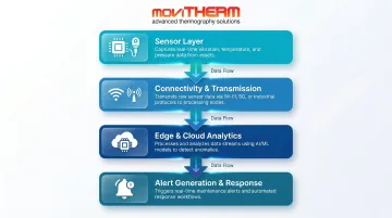
Sensor Layer: Data Collection at the Asset
Sensors are physically installed on or near the target equipment to continuously measure parameters such as vibration, surface temperature, pressure, acoustic emission, current draw, and humidity. Sensor type and placement are determined by the failure mode being monitored, not by convenience.
For example:
- Bearing wear manifests as increased vibration amplitude at specific frequencies, which requires an accelerometer mounted axially or radially on the bearing housing
- Overheating electrical connections produce localized temperature rise, which requires a thermal sensor with direct line-of-sight to the connection point
- Hydraulic system leaks generate ultrasonic noiseSensor selection directly impacts data quality. A vibration sensor on the wrong axis, or a temperature sensor misaligned with the thermal hotspot, can miss the exact failure signature it was deployed to catch. Proper coverage design — how many sensors, which types, and where — determines whether the system catches failures early or misses them entirely.
Connectivity and Data Transmission
Sensor data must travel from the field to a processing system. The connectivity method depends on data frequency requirements, physical environment, and distance to the gateway or processing node.
Common connectivity options:
- Wired protocols (Ethernet, Modbus, RS-485): Reliable, high-bandwidth, immune to radio interference — ideal for fixed installations where cable runs are feasible
- Short-range wireless (Wi-Fi, Bluetooth, IO-Link Wireless): Suitable for sensors within 10–100 meters of a gateway, in environments where cabling is impractical
- Long-range wireless (5G, LoRaWAN, cellular): Designed for remote assets, outdoor installations, or distributed facilities where sensors may be kilometers apart
The role of industrial gateways:
Gateways aggregate data from multiple sensors and convert it into a format compatible with cloud or edge platforms. This is typically where initial data filtering and compression occur to reduce bandwidth load.
A gateway might receive raw vibration waveforms from 20 accelerometers, extract RMS values and frequency spectra at the edge, and transmit only the processed features upstream — cutting data volume by 90% or more while preserving diagnostic value.
Edge Computing and Cloud Analytics
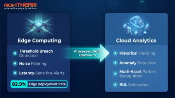
Edge computing refers to processing that happens locally — at the gateway or on-machine processor — before data reaches the cloud. Edge nodes detect threshold breaches, filter noise, and trigger time-critical alerts without waiting for round-trip communication to a distant server.
Benefits of edge processing:
- Reduced latency for safety-critical alerts (milliseconds instead of seconds)
- Lower cloud data costs by transmitting only significant events or processed features
- Continued operation during network outages
According to a systematic literature review, 82.9% of IoT data reduction solutions are deployed exclusively at the edge, addressing bottlenecks in network bandwidth, energy consumption, and cloud storage costs.
Cloud analytics layer:
Raw measurements become actionable insights at the cloud level. Cloud platforms perform:
- Historical trending across weeks, months, or years
- Anomaly detection using statistical models or machine learning
- Pattern recognition across multiple assets (for example, identifying that all motors on a production line are degrading simultaneously)
- Remaining Useful Life (RUL) estimation based on degradation rates
The cloud layer is where "what's happening" becomes "what to do next" — translating degradation trends into maintenance priorities before failures occur.
Alert Generation and Remote Response
Well-configured systems trigger alerts when monitored parameters cross defined thresholds or when analytics detect anomaly patterns. Effective alerts deliver enough context for a maintenance decision to be made remotely without a site visit.
What good alerts include:
- Which asset triggered the alert (asset ID, location, description)
- Which parameter exceeded limits (temperature, vibration, pressure)
- Current value and threshold setting
- Trend direction (rising, stable, falling)
- Suggested action (inspect, schedule maintenance, emergency shutdown)
Alerts are delivered via multiple channels — text message, voice call, email — to ensure the right person receives the notification regardless of location or work schedule. For example, MoviTHERM's iTL cloud monitoring solution provides 24/7 thermal surveillance with multi-channel alerting (text, voice, email) integrated into IIoT infrastructure.
Closing the response loop:
Alerts prompt either human review and scheduled maintenance, or automated control responses — for example, reducing motor load when temperature exceeds safe limits. The critical step is confirming whether the corrective action actually resolved the anomaly.
That feedback loop is what turns condition monitoring into a sustained reliability practice. When alerts are acknowledged but not acted on, or when actions fail to address the root cause, the system stops delivering value regardless of how well the sensors are configured.
Sensor Technologies That Power IIoT Condition Monitoring
While vibration analysis has historically dominated condition monitoring, modern IIoT systems use a multi-modal sensor approach. Different failure modes manifest in different physical signals, so the sensor mix should match the asset type and the failure modes being targeted.
Vibration sensors (accelerometers):
Bearing wear, imbalance, misalignment, and looseness all show up in vibration signatures before they cause visible damage. Accelerometers measure high-frequency oscillations—typically in the 10 Hz to 10 kHz range—and output raw waveforms that edge processing converts into actionable data.
Edge preprocessing converts raw waveforms into:
- RMS (root mean square) values representing overall vibration intensity
- FFT (Fast Fourier Transform) spectra revealing specific fault frequencies
- Peak values indicating impact events
According to industry data, continuous vibration monitoring typically detects bearing defects weeks before functional failure, providing ample lead time for maintenance planning.
Temperature and thermal sensors:
Surface temperature anomalies precede most electrical and mechanical failures. Overheating bearings, failing insulation, overloaded switchgear, and thermal runaway in battery systems all manifest as temperature deviations before visible damage occurs.
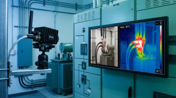
Non-contact infrared sensors and thermal cameras capture this data without production interruption. A single camera can monitor multiple components simultaneously—flagging hot spots that would otherwise require dozens of discrete sensors to cover. Common thermal monitoring targets include:
- Electrical panels and switchgear
- Conveyor systems and drive motors
- Process equipment and heat exchangers
- Battery modules and energy storage systems
Fixed thermal cameras integrated into IIoT architectures—such as the FLIR A50/A70 Smart Sensors and Optris PI 640i deployed by MoviTHERM—deliver 24/7 thermal surveillance with 640 × 480 resolution and thermal sensitivity below 40 mK. That translates to detecting temperature anomalies as small as 0.04°C, well before a fault becomes a failure.
Acoustic/ultrasonic sensors:
Acoustic emission sensors capture high-frequency elastic waves in the 20 kHz to 1 MHz range, making them effective for faults that produce no visible signal until failure is imminent. They work well for:
- Compressed air and gas leaks (which produce ultrasonic noise)
- Cavitation in pumps and hydraulic systems
- Crack propagation in pressure vessels and structural components
Pressure sensors:
Pressure transducers monitor hydraulic and pneumatic system health, detecting slow leaks, pump degradation, and valve failures. Even gradual pressure drift—a few PSI per shift—can indicate a developing seal failure weeks before output quality drops.
Electrical parameter monitoring:
Current, voltage, and power factor monitoring detects motor degradation, insulation breakdown, and load imbalances without adding any mechanical sensors to the asset. Motor Current Signature Analysis (MCSA) is most useful for motors in inaccessible locations—inside sealed enclosures, at height, or in hazardous areas—where physical sensor installation is impractical.
From Sensor Data to Remote Decision-Making
"Remote decision-making" means maintenance engineers and operations managers can view real-time parameter trends, historical data, and alert histories from any device, at any location—enabling maintenance scheduling, escalation, and resource dispatch without being on the plant floor.
Dashboards and cloud platforms consolidate multi-sensor, multi-asset data into a single view:
- Trend graphs showing parameter evolution over hours, days, or weeks
- Alert logs documenting when thresholds were breached and how teams responded
- Equipment health scores aggregating multiple parameters into a single metric
The ability to correlate data across multiple parameters significantly improves diagnostic confidence. A simultaneous rise in vibration and temperature on the same bearing provides much stronger evidence of impending failure than either parameter alone.
That quantified benefit is well-documented: a 2021 study in heavy industry found that multi-sensor predictive maintenance methods reduced false alarms by 90.25% on average compared to stand-alone outlier detection.
For thermal monitoring specifically, MoviTHERM's iTL cloud platform extends this capability with 24/7 image access, trend analysis, and multi-channel alerting—purpose-built for thermal surveillance systems integrated into IIoT infrastructure.
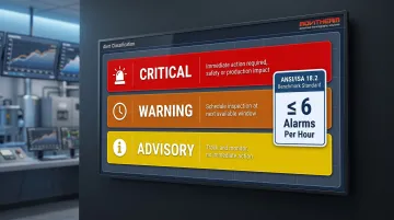
Poorly configured alert systems create as many problems as they solve. When operators receive too many notifications, they start ignoring them—a well-documented failure mode called alarm fatigue. Industry standard ANSI/ISA 18.2 defines measurable best practices:
- Fewer than 6 alarms per hour per operator (one every 10 minutes)
- 10+ alarms in any 10-minute period constitutes an alarm flood
- Poor alarm management contributes to over $20 billion in lost production annually (exida)
Well-configured systems distinguish between:
- Advisory alerts (track and monitor—no immediate action required)
- Warning alerts (schedule inspection during next available window)
- Critical alerts (immediate action required—potential safety or production impact)
This tiered approach reduces noise and ensures that when a critical alert arrives, it receives the attention it demands.
Where IIoT Condition Monitoring Delivers the Most Value
IIoT condition monitoring delivers the clearest ROI where the cost of unplanned downtime far exceeds the investment in continuous monitoring infrastructure. Four asset categories drive the strongest business case.
High-Value Rotating Equipment
Motors, compressors, turbines, and conveyors are critical to production throughput — when one fails, entire lines stop. Automotive manufacturing downtime costs $2.3 million per hour on average (Reliamag). Even a 10% reduction in unplanned stoppages translates to millions annually for a single facility.
Electrical Distribution Infrastructure
Switchgear, transformers, bus bars, and circuit breakers are among the hardest failures to anticipate with visual inspection alone. Electrical failures cause approximately 26% of industrial facility fires, yet thermal imaging can identify nearly 25% of those failures — specifically, heat anomalies at faulty connections — before they occur (Carelabz).
Process Equipment and Remote Assets
Two additional categories benefit consistently from continuous monitoring:
- Reactors, heat exchangers, dryers, furnaces: Equipment running 24/7 accumulates wear steadily. Small deviations compound over time, and continuous monitoring catches degradation trends early enough to schedule repairs during planned shutdowns — not emergency outages.
- Offshore platforms, utility substations, underground facilities: Manual inspection requires travel, permits, and safety protocols. Remote IIoT monitoring eliminates routine site visits, cutting both inspection costs and safety exposure.
Industries with the strongest business case:
| Industry | Avg. Cost per Hour | Annual Loss per Plant | Adoption Driver |
|---|---|---|---|
| Automotive | $2.3 million | $129 million+ | High-speed production lines; downtime stops entire facility |
| Oil & Gas / Refining | $500,000+ | $87 million | Safety risk; regulatory compliance; aging infrastructure |
| Pharmaceuticals | $500,000+ | $50 million+ | Regulatory batch integrity; quality control requirements |
| Heavy Industry | $187,500 | $45 million | Critical rotating equipment; long lead times for replacement parts |
Source: Siemens True Cost of Downtime 2024 via Reliamag
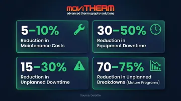
According to Deloitte, predictive maintenance programs reduce maintenance costs by 5–10%, cut equipment downtime by 30–50%, and lower unplanned downtime by 15–30%. Mature condition-based programs push that further — reducing unplanned breakdowns by 70–75%.
Conclusion
Effective IIoT condition monitoring depends on the right sensors, reliable connectivity, intelligent analytics, and fast alert pathways working together. When those layers align, machinery degradation gets caught early — before it becomes a failure.
Teams that understand the full stack — from sensor placement to alert configuration — deploy faster and experience fewer false alarms. Knowing how each layer functions, where data flows, and where vulnerabilities emerge also shapes better vendor selection and more effective troubleshooting.
The question is no longer whether to deploy IIoT condition monitoring, but how to deploy it correctly: with architecture, sensors, and decision logic that convert continuous data streams into fewer unplanned shutdowns and lower maintenance costs.
Frequently Asked Questions
What is industrial IoT condition monitoring?
IIoT condition monitoring is the continuous, automated tracking of machine health using networked sensors and connected systems—combining sensor data collection, network transmission, analytics, and alerting to enable remote visibility and predictive maintenance without manual inspection rounds.
What are the 5 elements of condition monitoring?
The five core elements are: (1) sensor-based data collection at the asset, (2) data transmission via wired or wireless networks, (3) data processing and analytics (edge and cloud), (4) alert generation when parameters deviate, and (5) maintenance response, either human action or automated control.
What sensors are used in industrial IoT condition monitoring?
The main sensor types include vibration sensors (accelerometers), temperature and thermal imaging cameras, acoustic and ultrasonic sensors, pressure transducers, and electrical parameter monitors (current, voltage, power factor). Sensor selection depends on the failure modes being targeted: bearing wear requires vibration sensors, while electrical faults call for thermal cameras or current monitoring.
What is the difference between CBM and PdM?
Condition-Based Maintenance (CBM) triggers maintenance actions based on actual measured equipment condition—responding when a parameter crosses a threshold. Predictive Maintenance (PdM) uses that condition data plus analytics and machine learning to forecast when failure will occur, enabling proactive maintenance scheduling before the failure happens.
How does IIoT condition monitoring reduce unplanned downtime?
By detecting early-stage failure signatures such as rising bearing temperature, increasing vibration amplitude, or abnormal current draw, IIoT systems give maintenance teams weeks of lead time to schedule repairs during planned windows rather than reacting to unexpected breakdowns.
Can thermal imaging cameras be used in an IIoT condition monitoring system?
Yes. Thermal cameras integrate into IIoT architectures, continuously monitoring electrical and mechanical equipment for heat anomalies. Images and trend data are accessible remotely via cloud platforms, and alerts are delivered automatically when thermal thresholds are exceeded—enabling 24/7 non-contact surveillance of critical assets.