MoviTHERM

About MoviTHERM

This author has not yet filled in any details.
So far MoviTHERM has created 156 blog entries.

Connecting Your FLIR (A50/A70/A400/A700) Camera to Your Network

How to Connect Your FLIR Camera to Your Network

Step-by-Step Guide: Connecting Your FLIR (A50/A70/A400/A700) Camera to Your Network

In this article, we will walk you through the steps on how to connect your FLIR camera to your network. We will cover how to find your computer’s subnet, how to locate your camera’s IP address, how to change your camera’s IP address, and optionally, how to change your computer’s IP address.

Video Overview

Materials You Need

To begin with, you will need the following components:

  • A FLIR camera that is properly powered and connected to the correct network.
  • A working computer that is also connected to the same network.
  • FLIR IP Config software (link to download)
  • A web browser.

Before we start, it’s important to note that if you’re having trouble turning on the device, refer to the previous article for instructions on proper power.

Step 1: Find Your Computer’s Subnet

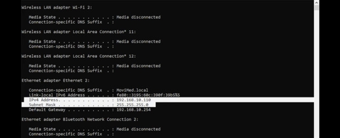
For devices to talk to each other in the same network, they must be within the same subnet. The subnet can be determined by using the command prompt application on Windows and entering the command “IP config.”

A subnet is a way to divide a big network into smaller ones. The subnet mask is a code that helps identify which part of the IP address belongs to the network and which part belongs to the device. In this example, the subnet mask is (255.255.255.0), which means that the first three sets of numbers of the IP address (192.168.10) is the network address known as the subnet. Any numbers after that are not important.

Step 2: Locate Your Camera’s IP Address

By default, most devices use a dynamic IP address known as DHCP mode and will automatically search for the correct IP address and the subnet to establish communications with the connected computer. The FLIR IP Config tool will list all compatible cameras on the subnet.

Alternatively, you can use the free Advanced IP Scanner tool to determine the camera’s IP address. To determine the IP address of your camera using the Advanced IP Scanner tool, follow these steps:

  1. Download and install the Advanced IP Scanner tool on your computer. (link to download)
  2. Open the tool and click “Scan.”
  3. Once the scan is complete, look for the FLIR camera on the list of connected devices.
  4. The camera’s IP address should be listed under the “IP Address” column.

Step 3: Change Your Camera’s IP Address (Optional)

If you need to change your camera’s IP address, use the FLIR IP Config tool.

Here’s how:

  1. Open the FLIR IP Config tool and select your camera from the list of compatible cameras.
  2. Click on “Edit” to open the camera’s settings.
  3. In the “Network” tab, you can change the camera’s IP address to your desired address.
  4. Click “Save” to apply the changes.

Step 4: Change Your Computer’s IP Address (Optional)

If you need to change your computer’s IP address, you can do so by following these steps:

  1. Open the Control Panel and select “Network and Sharing Center.”
  2. Click on “Change adapter settings.”
  3. Right-click on the network adapter that you’re using and select “Properties.”
  4. Select “Internet Protocol Version 4 (TCP/IPv4)” and click on “Properties.”
  5. In the “General” tab, select “Use the following IP address” and enter your desired IP address, subnet mask, and default gateway.
  6. Click “OK” to apply the changes.

Conclusion

In conclusion, connecting your FLIR camera to your network is a simple process that can be completed by following the steps outlined in this article. With your camera connected to your network, you can begin to explore the many features and capabilities.

2024-08-30T16:28:08-07:00Friday, August 30, 2024|Support|

FLIR Camera Interface: Measurement Tools (A50/A70/A400/A700) Cameras

FLIR Web Interface: A Guide to Using Measurement Tools

Quick Walkthrough for (A50/A70/A400/A700) Cameras

Thermal imaging is a valuable technology that has revolutionized many industries by enabling the detection of heat signatures that cannot be seen by the human eye. FLIR cameras are a popular choice for thermal imaging and come equipped with a variety of measurement tools that can be used to accurately capture and analyze temperature data.

In this article, we will explore the different measurement tools available within the FLIR web interface and explain how they can be used to improve the accuracy and efficiency of your thermal imaging experience. Whether you’re a seasoned thermal imaging professional or just starting out, this guide will provide you with the knowledge you need to make the most of your FLIR camera.

Video Overview

FLIR Measurement Tools

It’s important to note that the availability of measurement tools may vary among different models of FLIR cameras. Therefore, it is recommended to verify the model number and configuration of your camera to determine which measurement tools are supported.

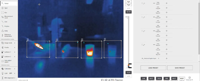
Once you have accessed the FLIR web interface by entering the camera’s IP address into your web browser and logging in, you will see the measurement tools labeled with a number for identification.

The measurement tools are numbered according to the order of their creation.

Added measurements will show up in the active measurement section, where the measurement temperatures are displayed and managed.

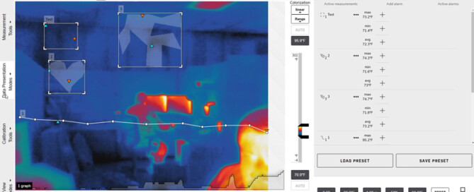
Select Tool

The select tool, an essential tool in temperature measurement, allows you to perform various actions such as moving, editing, or deleting any existing measurement tool on the image. It gives you the flexibility to modify the measurement tool to suit your needs without affecting the other measurement tools on the image.

Spot Tool

The spot tool is a temperature measurement tool that displays the temperature reading of a specific spot in the image. This tool is useful when you need to measure the temperature of a specific area in the image with high precision.

Box Tool

The box tool displays the minimum, maximum, and average temperature within a selected rectangular area of the image. It is particularly useful when measuring the temperature of a large area in the image.

Measurement Mask Tool

The measurement mask tool is used to capture and measure more complex shapes in the image. This tool shows the minimum temperature, maximum temperature, and average temperature within a selected shape of the image, making it ideal for measuring irregularly shaped objects.

Line Tool

The line tool shows the minimum temperature, maximum temperature, and average temperature on the selected line. It is particularly useful when measuring temperature variations along a specific path.

Poly Line Tool

The poly line tool is similar to the line tool, but it allows you to measure temperature variations along a series of connected lines drawn on the image. It displays the minimum temperature, maximum temperature, and average temperature within the poly line.

Delta Tool

The delta tool is used to calculate the difference between two temperature measurements or between a temperature measurement and a fixed temperature known as the reference temperature. This tool is particularly useful when measuring temperature variations over time or comparing two different areas in the image.

Conclusion

It’s important to remember that each of these tools has its unique features, and they can help you achieve more precise results when used correctly. With proper utilization of these tools, you can enhance your thermal imaging experience and obtain the best possible results. Remember to verify your camera’s model number and configuration to determine which measurement tools are supported. By understanding each tool’s features and how to use them effectively, you can get the most out of your FLIR camera.

2024-08-30T16:29:10-07:00Friday, August 30, 2024|Support|

FLIR Camera Interface: Thermal Color Palettes & Data Presentation Modes (A50/A70/A400/A700) Cameras

How to Use Data Presentation Modes and Color Palettes

Quick Walkthrough for FLIR (A50/A70/A400/A700) Cameras

Thermal imaging cameras are an essential tool in many industries, from electrical inspections to building diagnostics. However, interpreting thermal data can be challenging if you don’t understand how to present the data properly. In this tutorial, we will explore the different data presentation modes and color palettes in thermal imaging and how they can impact your interpretation of the data.

Video Overview

Logging in to the Web Interface

To begin, type in the camera’s IP address directly into the camera’s web browser, and use the proper login credentials to log in to the web interface. If you’re having trouble turning on or connecting to the device, please refer to the previous article: How to Connect Your FLIR Camera to Your Network for instructions on proper power-up and network connection.

Upon logging in, you’ll be given the camera tab, which contains all settings associated with live streaming, alarms, analytics, and camera control.

Image Mode

Some FLIR cameras are able to capture both thermal and visual images simultaneously by selecting image mode within the web interface. You can choose which type of image is displayed on the screen. Please note, this feature is only available to FLIR devices with both visual and thermal cameras built-in.

Thermal Image Mode

Thermal image mode is when the camera displays a fully thermal image. In this mode, the color palette is an essential part of interpreting the data. Different color palettes highlight different temperature ranges, making it easier to identify areas of interest.

Thermal MSX Mode

Thermal MSX mode, also known as multispectral dynamic imaging mode, is when the camera displays a thermal image where details from the visual image have been added. This mode combines the best of both worlds: thermal and visual data. The thermal data highlights temperature differences, while the visual data provides context.

Digital Camera Image Mode

Digital camera image mode is when the camera displays a visual image captured by the digital camera. This mode is useful when you need to compare the thermal image to a visual reference.

Thermal FSX Mode

Thermal FSX mode, also known as flexible scene enhancement mode, is when the camera displays a thermal image with enhanced image details. In this mode, the camera fuses the thermal data with a high-resolution visual image. This mode is particularly useful for identifying small details in an image.

Differences Between Thermal MSX and Thermal FSX

One may wonder what the differences are between MSX and FSX modes. The FLIR thermal MSX mode enhances the overall image by overlaying thermal data on top of a visual light image. The FLIR FSX mode enhances a specific area of the thermal image by fusing it with a high-resolution visual image.

Conclusion

In conclusion, choosing the right data presentation mode and color palette is essential for interpreting thermal data correctly. A well-chosen palette and data presentation mode can bring new insights and clarity to your data, while poor choices can lead to more confusion. By understanding the different modes and palettes, you can optimize your thermal imaging workflow and make better-informed decisions.

2024-08-30T16:29:41-07:00Friday, August 30, 2024|Support|

How to login to the FLIR Camera Interface for (A50/A70/A400/A700) Cameras

How to login to the FLIR Camera Web Interface

Quick Walkthrough for (A50/A70/A400/A700) Cameras

FLIR cameras are used for various applications, including surveillance, industrial inspections, and research purposes. To access the camera’s features and settings, users need to log in to the camera’s web interface. This process involves using the camera’s IP address and login credentials, which can be found on the FLIR calibration certificate. In this support article, we will guide you through the steps to log in to the FLIR camera’s web interface, locate the factory default login credentials, and change the user login credentials. By following these steps, you can access and customize your FLIR camera’s settings and optimize its performance.

Video Overview

Required Materials

Before we begin, you will need the following items:

  • The IP address of the FLIR camera
  • A working computer that is connected to the same network as the camera
  • A web browser
  • FLIR calibration certificate to determine the default login credentials

Now that you have these items ready, let’s proceed to the steps:

Step 1: Accessing the Camera’s Web Interface

  • Type the camera’s IP address directly into the web browser on your computer.
  • Ensure the camera is connected to the network and properly powered.

If you are having trouble connecting the camera to your network, please refer to our previous article: How to Connect Your FLIR Camera to Your Network

Step 2: Locating the Factory Default Login Credentials

FLIR cameras come with a calibration certificate. Check the back of the certificate for the factory default user web login credentials.

Please note: The characters “1”, lowercase “l” and uppercase “I”, as well as “0” and “O”, may look similar in the calibration certificate’s font text.

If you can’t find your FLIR calibration certificate, please contact us with the model and serial number. We will assist you in obtaining your default login credentials by working with FLIR.

Step 3: Changing the Login Credentials

To change the login credentials, log in to the web interface and click on the “Administration” tab located at the top of the screen.

Then, click on the “User Management” tab on the left.

Here, you can add, delete users, change roles, and passwords.

Conclusion

In conclusion, the FLIR camera’s web interface provides an efficient way of managing your camera’s settings and configurations. By following the steps above, you can easily log into the web interface and manage your camera effectively.

2024-08-30T16:30:27-07:00Friday, August 30, 2024|Support|

Proper Ways to Power Up Your FLIR (A50/A70/A400/A700) Camera

Proper Ways to Power Up Your FLIR Cameras: A Step-by-Step Guide

Proper ways to power up FLIR (A50/A70/A400/A700) cameras: PoE and Direct Connection methods explained.

In this guide, we will discuss two methods of powering FLIR a50, a70, a400, and a700 cameras: Power over Ethernet (PoE) and Direct Connection. We will explain the materials required for each method, step-by-step instructions on how to connect and power the camera, and how to check if the camera is receiving proper power and functioning. So, whether you’re setting up a new FLIR a50, a70, a400, or a700 camera or troubleshooting an existing one, read on to learn about the proper ways to power up your FLIR camera.

Video Overview

Power Over Ethernet (PoE)

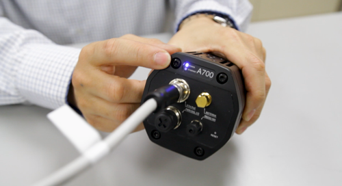
Materials required to run your camera using PoE include a FLIR camera, Ethernet cable, FLIR M12 to RJ45 Adapter Cable, and proper power input to the camera’s Ethernet port.

It is important to note that the camera must be connected to the output to receive power, while the input is used to connect to your network source.

Here are the steps to properly connect and power your camera using PoE:

  1. Connect the Ethernet cable to the adapter cable on the back of the camera.
  2. Connect the other end of the Ethernet cable to the PoE switch or injector.
  3. Check the camera’s power/error indicator LED to verify that it is receiving proper power and functioning.

Power via Direct Connection

Materials required for power via direct connections include a FLIR camera, color-coded breakout cable to the M12 port, and a power supply providing 48 or 24 VDC.

Here are the steps to properly connect and power your camera via direct connection:

  1. Connect the color-coded breakout cable to the M12 port labeled PWR/DIG I/O.
  2. The other end of the cable has exposed wires that can be used to apply a voltage.
  3. Connect wires one and two to a 24 or 48 VDC power supply.
  4. Check the camera’s power/error indicator LED to verify that it is receiving proper power and functioning.

LED Indications and What They Mean

It is important to understand the different LED indications on your FLIR camera and what they mean. The power/error indicator LED indicates whether the camera is receiving proper power and functioning.

Here are the different LED indications and what they mean:

  1. Green LED: The camera is receiving proper power and functioning normally.
  2. Yellow LED: The camera is in the process of powering up or initializing.
  3. Red LED: The camera is not receiving proper power or is experiencing an error.

Conclusion

Properly powering up your FLIR camera is essential to ensure that it functions correctly. In this guide, we discussed the proper ways to power up your FLIR smart cameras, including power over Ethernet, power via direct connection, and the different LED indications and what they mean. By following these steps, you can ensure that your FLIR camera is receiving proper power and functioning as it should.

2024-08-30T16:31:00-07:00Friday, August 30, 2024|Support|

Adding/Configuring Alerts and Automated Reports in the iTL Platform

How to Add and Configure Automated Reports in the iTL Platform

Configuring Automated Reports on iTL: A Step-by-Step Guide

In this tutorial, we will explain how to add and configure automated reports on your iTL system. This feature is useful for monitoring and analyzing data over time, and you can schedule reports to be delivered to your email inbox at any time and frequency. By following the steps outlined in this guide, you can optimize your iTL system’s automated reporting capabilities to ensure that you receive timely and accurate notifications and reports, allowing you to stay on top of your operations and make informed decisions.

Video Overview

Configuring Notification Recipients

Any alert instance can send notifications via email, SMS, or voice call if enabled at the facility. These are configured in the notification tab of each alert. To do this, navigate to an alert that has been configured for a device and click on the notification tab.

On this tab, you can enter emails, phone numbers for SMS alerts, and phone numbers for voice alerts. To save time, you can add contact groups and individual contacts saved in the address book section of the Settings tab.

It’s important to know that contacts entered in an alert will be notified for that alert, which is configured for a single device.

Phone numbers should include the country code for both voice alerts and SMS.

Voice alerts, if enabled, may come from new phone numbers each time, depending on the region.

Voice alert phone calls do not leave voicemail, so it is recommended to pair voice alerts with an SMS alert.

Email notifications may appear in spam, so it’s recommended to whitelist notifications@cloud.studio.

Configuring Automated Reports

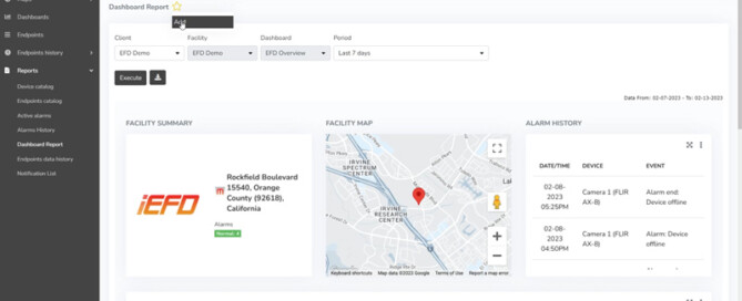
Report data can be saved as PDF or CSV using the download icon once the report has been executed with parameters.

To schedule a report delivery over email, click on the report section on the monitor page’s left side.

Select the favorite icon on the desired report to set up a report, then add it.

In the configuration screen, set up the relevant parameters and check “Enable scheduling for this report”.

You will be able to select the type of file to export and schedule it for any day of the week and time.

Multiple favorite reports can be created per alarm condition.

To delete or edit an automated report, select the favorite icon again, then click on the three dots on the right-hand side of the schedule.

Conclusion

We hope that this support article has provided you with the necessary information on how to add and configure automated reports in the iEFD platform. Remember, if you still need assistance or have further questions, our support team is always here to help. By following the tips and guidelines outlined in this article, you can ensure that you are using our product to its fullest potential and enjoying a seamless user experience.

If you have any questions or need assistance, please contact us at info@movitherm.com.

2024-08-30T16:32:12-07:00Friday, August 30, 2024|Support|

Temperature Monitoring with iTL: Understanding ROI Processing and Data Uploading

Understanding ROI and Temperature Data Management System in iTL Platform

Mastering Temperature Monitoring on MoviTHERM iTL Platform: Region of Interest (ROI) and Temperature Data Management System

If you’re using the MoviTHERM iTL platform for temperature monitoring, it’s essential to understand how to set the region of interest (ROI) and manage temperature data. In this tutorial, we’ll go over practical examples that demonstrate how the iTL platform processes and uploads temperature data within the predefined ROIs.

Video Overview

Setting the Region of Interest on iTL

When setting the ROI in your iTL system, you can choose a large array or multiple smaller ones within a thermal image. All ROI information will be sent to the cloud as a group rather than individually for each box. Therefore, it’s crucial to consider whether to use thermal data from the entire image or only specific areas.

If any pixel in the ROI exceeds the temperature limit, the alarm will activate.

To avoid areas with high activity, ensure you have a clear understanding of the scene and which areas to exclude.

Example #1: ROI Drawn Around Unique Objects

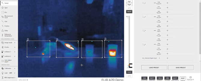
In this example, you will observe four unique objects within the field of view of the camera. An ROI has been drawn around each object, with different maximum temperature values in each ROI.

On the cloud platform, you will see that the highest maximum temperature among the four ROIs is reported.

Example #2: Changing the Arrangement of Objects

In the next example, the arrangement of the unique objects has been changed.  When you view the cloud platform, you will observe that the highest maximum temperature among the four ROI is still being set regardless of their order.

Example #3: Removing an ROI Box

In this example, one of the four ROI boxes has been removed. The object that has been registered as the hottest up to this point is now outside of all active ROIs.

As a result, when looking at the device in the cloud platform, we see the temperature has dropped down. It is currently reporting the hottest object within the current ROIs.

Managing Temperature Data

In some scenarios, there may be specific pieces of equipment you want to monitor for overheating, although there are other objects in the image. The iTL platform allows you to set the ROIs and manage temperature data according to your specific needs. By understanding how to set the ROIs and manage temperature data, you’ll have a thorough understanding of the iTL systems, functions, and capabilities.

Conclusion

In conclusion, setting the ROI and managing temperature data are crucial steps to ensure accurate temperature monitoring on the iTL platform. With the practical examples provided in this tutorial, you can effectively use the iTL platform for temperature monitoring according to your specific needs.

2024-08-30T16:32:45-07:00Friday, August 30, 2024|Support|

Updating Alarm Thresholds in the iTL Platform

Managing Alarm Thresholds on the iTL Cloud Platform

Learn How to Set and Configure Temperature Thresholds and Notifications for Effective Alarm Management

Managing alarms and alerts is critical for ensuring the proper functioning of you iTL platform and the safety of your facility. In this article, we will guide you through the process of updating and managing the alarm thresholds on your iTL platform. We will cover different alert types, temperature thresholds, and notification settings, and provide step-by-step instructions for setting up and managing the thresholds. By the end of this tutorial, you will have a better understanding of how to manage your alarms on the iTL platform, ensuring that you are alerted in a timely manner in case of any critical events.

Video Overview

Alarm Thresholds

Each device temperature endpoint has an alarm threshold, which can be set individually in the alerts configuration page of the iTL platform. It’s important to note that the same configuration page is used to set up email and phone notifications for each alert. Therefore, these configurations should be edited carefully by users with administration privileges, especially if there’s any doubt about the alert configuration in your facility.

Types of Alerts

A device can have two types of alerts: critical temperature threshold and warning temperature threshold. The critical temperature threshold indicates a fire alarm and should be limited to one per device endpoint. On the other hand, the warning temperature threshold is for non-critical notification use, providing situational awareness and early warning. Multiple warning thresholds can be set per endpoint.

Accessing Critical Temperature Threshold Settings

To access the critical temperature threshold settings, log in to the MoviTHERM iTL Cloud platform page with a user who has administration privileges.

Click on the settings page located on the top right with the gear icon, navigate to alarms on the left-hand side, then click on alerts.

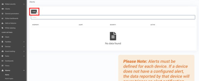
Click on the add button to add an alert, and define alerts for each device.

If a device doesn’t have a configured alert, the reported data won’t trigger a notification.

Configuring Critical Temperature Thresholds

After clicking the add button, you’ll be given different options and settings to configure.

First, choose the endpoint option, click and choose the device you want to add an alert to, then click on the variable option.

Choose temperature for the condition, and select greater than option with the temperature set at a value where fire is considered likely determined for use specific setting for normal condition.

Choose lower than option with the temperature set at a value that is determined to be at the highest normal temperature range.

The severity level option should be set to medium high, which is reserved for device offline alarms.

Notifications

Notifications can be sent via email, SMS, or phone call if enabled at the facility. These are configured in the notification tab of the alert to ensure proper notification.

Please note that the following contacts entered in an alert will be notified for that alert, which is configured for a single device.

Phone numbers should include the country code for both voice alerts and SMS.

Voice alerts, if enabled, may come from new phone numbers each time depending on the region.

Email notifications may appear in spam, so it’s recommended to whitelist notifications@cloud.studio.

Adding/Configuring Non-Critical Temperature Thresholds

Alerts with severity set to low and without the gateway tag are considered non-critical but still important for situational awareness. Warning thresholds can be set per device, so relevant personnel can be notified separately of rising temperatures before they reach a critical threshold. There’s virtually no limit to the number of low severity alarms that can be configured per device.

To add/configure non-critical temperature thresholds, click on the add button. You’ll be given different options and settings to configure.

First, choose the endpoint option, click and choose the device you want to add an alert to, then click on the variable option.

Choose temperature for the condition, and select greater than option with the temperature set at a value where a low severity alert is considered likely for normal condition.

Choose lower than option with the temperature set at a value that is determined to be the highest normal temperature range.

The severity level option should be set to low if you like to delay the alert being triggered after a condition has been observed for a specific time.

Conclusion

Properly managing and updating alarm thresholds is crucial for ensuring optimal performance and safety on the iTL platform. In this tutorial, we have covered the different types of alerts, temperature thresholds, and notification settings. We have also walked you through the process of setting up and managing thresholds, including critical and non-critical temperature thresholds. By following the steps outlined in this article, you can ensure that your devices are configured with the appropriate temperature thresholds and notifications to keep your facility safe and running smoothly. If you have any further questions or need assistance, please do not hesitate to contact us at info@movitherm.com.

2024-08-30T16:33:19-07:00Friday, August 30, 2024|Support|

How to set up the IP address on the MoviTHERM MIO

Set up the IP Address on the MoviTHERM MIO

This video shows you how to set the device IP address on your MoviTHERM MIO.

The MoviTHERM MIO Series – Intelligent I/O Module for FLIR® Cameras – supporting one of the following Camera models: FLIR AX8, FLIR FC Series R or FLIR A310

Remote Monitoring Applications Made Simple

More info about the MoviTHERM MIO Series Intelligent I/O Modules

Before we get started, there is one thing to keep in mind: If you change the MIO’s IP address, just remember that any cameras connected to your MIO network must be on the same subnet as the MIO. So, that means if you change the MIO subnet, you may also need to update the camera IP addresses accordingly.

Ok, let’s get started. First, we need to open a browser window and log into your MIO. So, let’s launch the Google Chrome browser, key in the default MIO IP address, which is 192.168.1.2, and then log in to the MIO. The default MIO password is “password” so let’s type that in and open the Device Settings page.

The Device IP Address field is located toward the bottom of the settings page, under the Network Configuration heading. Just key in the new IP address (and Subnet mask if necessary), then click, “Save Settings and Reboot”.

After the MIO reboots, we can log-in again to verify the change. And there it is!

That’s all you need to do to set the IP address on your MoviTHERM MIO!

Thanks for watching, and remember to view the other how-to videos in this series for additional tips on setting up your MIO system!

2024-08-30T15:58:30-07:00Thursday, March 21, 2024|Support|

How to set up a digital output on the MoviTHERM MIO

Set up a Digital Output on the MoviTHERM MIO

This video shows you how to set up a digital output channel on the MoviTHERM MIO.

The MoviTHERM MIO Series – Intelligent I/O Module for FLIR® Cameras – supporting one of the following Camera models: FLIR AX8, FLIR FC Series R or FLIR A310

Remote Monitoring Applications Made Simple

More info about the MoviTHERM MIO Series Intelligent I/O Modules

We start with the assumption that you have already set up an inspection region in your camera. If you haven’t configured your camera yet, other videos in this series can help get you started. Please view them and set up your camera first before watching this video.

Ok, now that you have an inspection region set up in your camera, the first step is to open a browser window and log into your MIO. We will launch the Google Chrome browser, key in the default MIO IP address, which is 192.168.1.2, and log in to the MIO. The default MIO password is “password” so let’s type that in and get started.

Once we have logged in, we want to select the “Script Commands” tab. Click on the tab, and select a command for digital channel 0. We want to set an alarm based on the maximum temperature of an inspection region, so we will select the “Box Max Temperature” option, and then map ROI 1 to the Channel zero output. Next, we need to set the temperature limit for the alarm. We set a temperature limit of 30 degrees Celsius, and save the configuration to store and activate the alarm.

If we jump over to the Debug Page, we can see that our alarm is now responding and setting the Channel 0 output as expected.

That’s all you need to do to configure a digital output channel on the MoviTHERM MIO.

View the other how-to videos in this series for additional tips on setting up your MIO system!

2024-08-30T15:58:16-07:00Thursday, March 21, 2024|Support|
Go to Top