MoviTHERM

About MoviTHERM

This author has not yet filled in any details.
So far MoviTHERM has created 132 blog entries.

Seal Strength Testing Using Thermal Cameras in Your Process Line

Seal Strength Testing Using In-Line Thermal Inspection

In the realm of manufacturing precision, the assurance of product packaging integrity takes center stage. Using thermal cameras for in-line seal strength testing has revolutionized quality control and efficiency in the packaging industry.

Why Seal Strength Tests Matter

Seal strength tests are vitally important in manufacturing because they determine how well product packaging holds up. The results significantly affect how long products like food, beverages, and pharmaceuticals stay fresh and safe.

Ensuring that package seals are strong is not just a routine step but a crucial measure to prevent issues like leaks and contamination. Seal strength tests play a key role in safeguarding product quality, reducing waste, and maintaining customer satisfaction.

Traditional Seal Strength Testing Methods and Their Challenges

Traditional seal strength testing methods have long been the stalwarts of quality control in manufacturing, yet they come with inherent challenges. These methods often involve sampling a limited number of packages, leaving a substantial portion unchecked and potentially harboring defects.

The use of vacuum chambers, for example, while effective in detecting leaks, is time-consuming and introduces the possibility of human error. Placing packages in a vacuum chamber and submerging them in water to detect leaks may not address all packages produced, leading to undetected faults that could compromise product quality.

As industries evolve and demand higher quality, the limitations of these conventional approaches become more apparent, paving the way for innovative solutions like in-line seal strength testing using thermal cameras.

Using Thermal Cameras for Seal Strength Testing

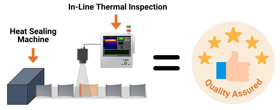
Thermal cameras are an effective tool for checking package seals right on the production line. Thermal cameras examine the seals of packages right after they’ve been heat sealed. They detect temperature differences on the surface of the packaging, essentially “seeing” the leftover heat from the sealing process. With real-time analysis, it speeds up the production line, making the packaging process more efficient.

Integrating thermal cameras into the production line ensures a fast and consistent inspection process. Using this method helps cut downtime by quickly spotting and fixing defective packaging before it causes disruptions. By implementing thermal cameras into your process line, you can automate your inspection process to provide reliable results. This lowers the risk of human error that can happen with manual inspections.

In-line thermal seal inspection brings advanced technology right into the heart of the production process. It raises the bar for quality control and ensures that every packaged product meets the highest standards of safety and reliability.

Packages Suitable for Thermal Inspection

Thermal seal inspection can work for different types of packaging, such as:

  • Flexible Packaging – This includes pouches, bags, and sachets made from plastic films, aluminum foil, and paper.
  • Rigid Packaging – This includes trays, clamshells, and blisters made from plastic, glass, and metal materials.
  • Sealed Containers – This includes cans, jars, and bottles made from glass, plastic, and metal.
  • Pharmaceutical Packaging – This includes blister packs, pouches, and bottles used for medication.
  • Food Packaging – This includes trays, bags, and bottles used for food and beverage products.

MoviTHERM TSI for Heat Seal Testing

MoviTHERM’s TSI is a seal inspection system that uses a thermal camera to assess the quality of heat seals. The automated inspection system compares unknown package seals to known good seal profiles and reliably detects good and bad seals. MoviTHERM TSI has an integrated recipe manager that allows the system to store hundreds of inspection scenarios. It also allows for system adaptation to various packaging seal inspection applications.

Core features of MoviTHERM TSI include:

  • Infrared Cameras that view and measure thermal variations of good and bad seals without contact.
  • Hardware and software that easily integrates with existing production equipment.
  • Advanced and reliable inspection logic pre-programmed for multiple packaging scenarios.
  • Image and data logging for traceability of performance.

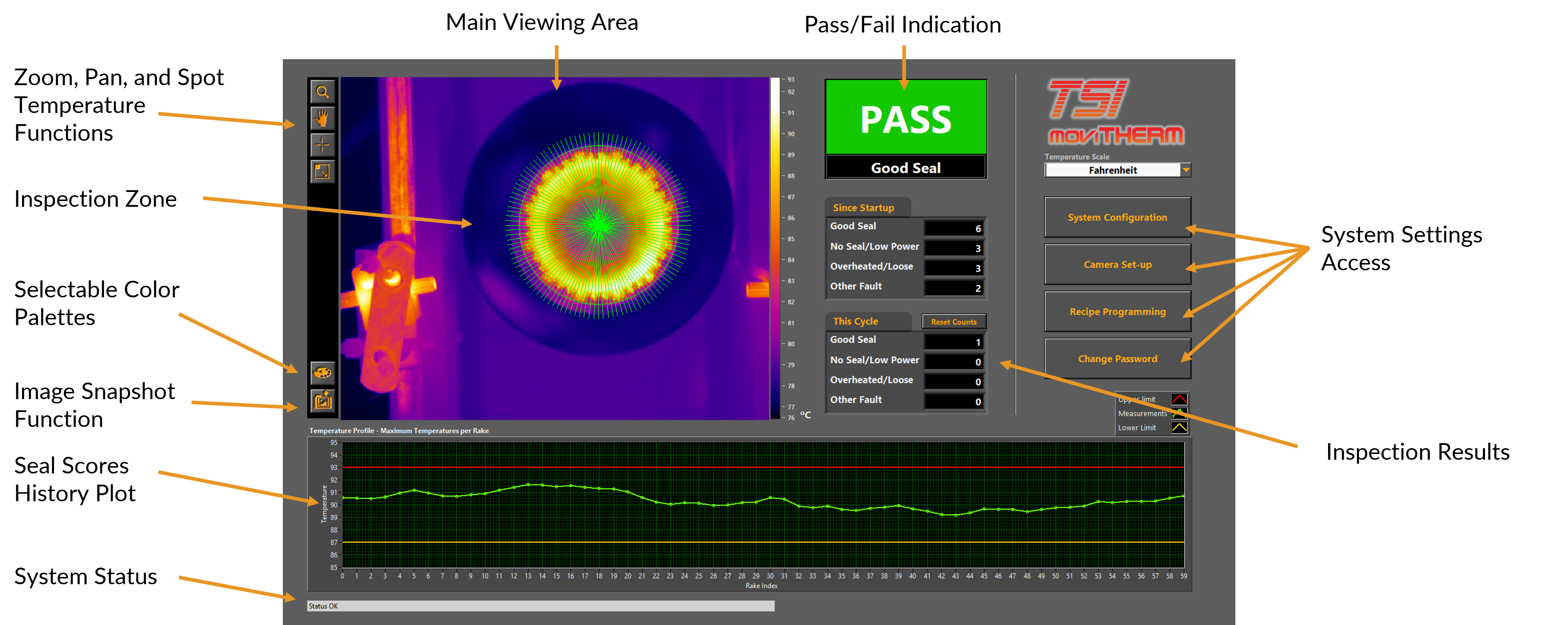
TSI Inspection Software

The TSI user interface is designed to be user-friendly and accessible through touch screen technology. All buttons and features on the interface can be easily operated by simply touching the screen.

In this particular example, the TSI user interface is being used to inspect bottle caps. The interface provides a visual representation of the inspection process, allowing the user to easily identify any issues or defects.

One of the key features of the TSI user interface is the thermal image display. In this example, the thermal image shows a bright yellow ring around the bottle cap. This indicates that the seal on the cap is good and meets the required standards.

To further confirm the quality of the seal, the interface also includes an indication window. In this window, a green “PASS” message is displayed, indicating that the seal has passed the inspection and is considered to be of high quality.

Overall, the TSI user interface provides a comprehensive and intuitive platform for inspecting bottle caps. Its touch screen accessibility and clear visual indicators make it easy for users to navigate and interpret the inspection results.

TSI Software Display

What’s Included with MoviTHERM TSI?

MoviTHERM TSI solution provides 100% in-line, high-speed integrity inspection for heat-related production lines.

The system includes:

  • High performance thermal camera
  • Standard powder-coated Industrial Electrical Enclosure (Optional
  • Stainless-Steel enclosure for food & beverage or pharmaceutical environments)
  • Touch-Screen PC and application specific software GUI interface
  • Interactive inspection Recipe Programmer to accommodate multiple products – or to try different “what-if” scenarios
  • Robust bi-directional PLC interface to transfer status messages and
  • PASS/FAIL results to a plant PLC (Ethernet/IP or Modbus)
  • Image FTP to transfer fault images to a remote server for off-line review

Use Case Examples

Thermal Seal Inspection (TSI) emerges as a highly effective solution for ensuring the integrity of various types of packaging sealed with heat. This innovative technology plays a pivotal role in maintaining the quality and safety of packaged products, particularly in industries like food, beverage, and pharmaceuticals.

Let’s delve into specific applications of TSI and how it contributes to the inspection of different types of sealed packages:

MoviTHERM TSI for Bag Seal Integrity Inspection

Bag Seal Integrity Inspection

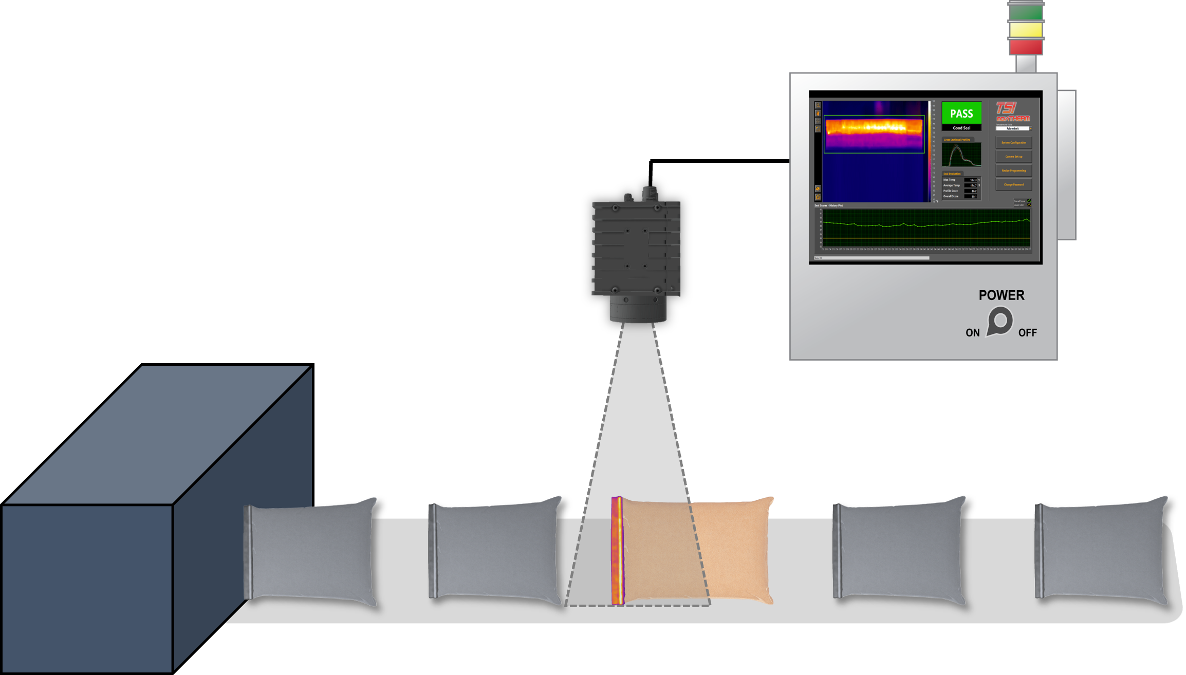
  • Scenario: Bags leaving the heated press or sealed with hot glue.
  • How it Works: TSI capitalizes on the residual heat retained by bags after the sealing process. This residual heat serves as a key indicator that can be accurately detected and inspected by TSI. The technology ensures that the seal conditions are thoroughly evaluated, providing insights into any potential faults.
MoviTHERM TSI for Bottle Cap Seal Integrity Inspection

MoviTHERM TSI for Bottle Cap Seal Integrity Inspection

Bottle Cap Seal Integrity Inspection

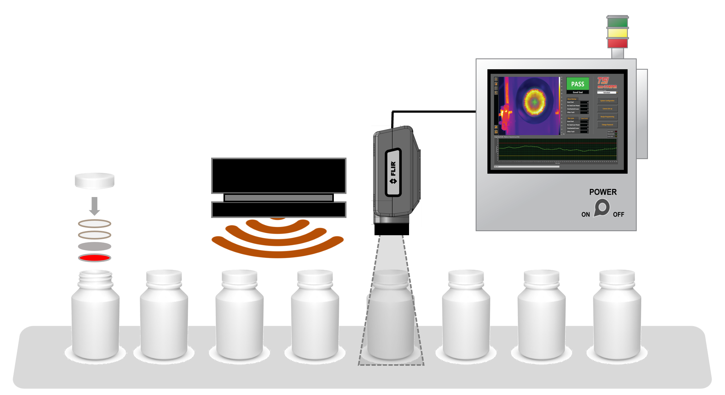
  • Scenario: Induction sealer creating heat in the foil section of the sealing packet.
  • How it Works: TSI extends its capabilities to assess the integrity of bottle cap seals. In instances where an induction sealer generates heat in the foil section during the sealing process, TSI steps in to evaluate the residual heat. This evaluation aids in identifying the seal condition and detecting specific fault types, if present.
MoviTHERM TSI for Pouch Seal Integrity Inspection

MoviTHERM TSI for Pouch Seal Integrity Inspection

Pouch Seal Integrity Inspection

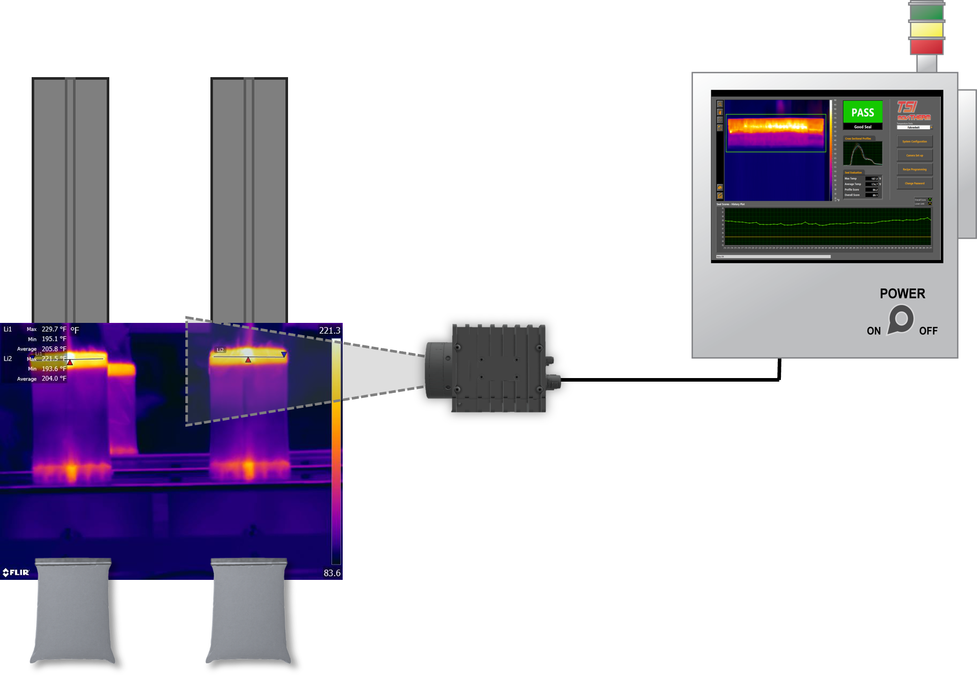
  • Scenario: Seams formed by heat and pressure in pouch-forming processes.
  • How it Works: TSI proves invaluable in assessing seams created through a combination of heat and pressure in pouch-forming processes. By comparing the thermal profiles of test samples to known non-leakers, TSI efficiently detects leaks in pouches. This method ensures a comprehensive evaluation of pouch seal integrity.
MoviTHERM TSI for Package Seal Integrity Inspection

MoviTHERM TSI for Package Seal Integrity Inspection

Thin Film Plastic Covered Packages Inspection

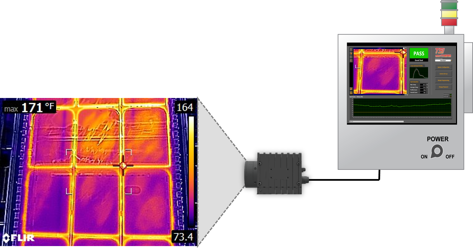
  • Scenario: Common in the food industry.
  • How it Works: TSI excels in the inspection of thin film plastic-covered packages, a prevalent packaging type in the food industry. This technology swiftly and reliably identifies the seal area, allowing for the detection of seal integrity. This is particularly critical for ensuring the safety of food products, providing consumers with confidence in the quality of packaged items.

Conclusion

Thermal cameras for in-line seal strength testing have revolutionized quality control. Seal strength tests are vital for products like food and pharmaceuticals. Traditional testing has limitations, making way for innovative in-line thermal camera testing. This real-time approach on production lines reduces downtime, cuts waste, and improves product quality.

MoviTHERM’s TSI system is a leading solution for this. It ensures reliability and safety across various packaging types. In-line thermal seal inspection with thermal cameras proactively enhances quality control, prevents defects, and meets industry standards.

2024-03-27T17:00:29-07:00Thursday, March 21, 2024|Blog|

Overcoming the Frustration of Unreliable Heat Sealers

The Ultimate Solution to Unreliable Heat Sealers

The Importance of Reliable Heat Sealing in Automation

One key component often responsible for sealing the deal (literally) in automated packaging processes is the heat sealer. However, despite advancements in technology, the frustration stemming from unreliable heat sealers remains a real concern for industries relying on flawless packaging.

A reliable heat seal guarantees freshness, prevents contamination, and maintains the overall quality of the contents. Inconsistent or faulty seals can lead to costly consequences such as product spoilage, recalls, and reputational damage. This article delves into the challenges posed by unreliable heat sealers and explores the solution of real-time thermal seal inspection systems to alleviate these concerns.

The Frustration of Unreliable Heat Sealers

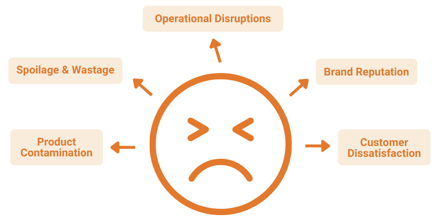
Unreliable heat sealers can lead to a cascade of issues. Operators may experience frequent interruptions in the production line due to resealing or rejecting improperly sealed packages. This not only hampers productivity but also increases operational costs.

Inconsistent seals can cause leakage, compromising the safety of products and potentially damaging brand trust. The frustration of dealing with these challenges highlights the need for a more dependable solution.

frustrations of heat sealing problems

Types of Heat Sealer Technologies

Not all sealing machines are created equal, and understanding the different technologies available can shed light on the reliability spectrum. Here are the main types of heat sealer technologies:

Impulse Sealers

Suitable for low-volume applications, these sealers heat up only during the sealing process.

Continuous Sealers

Ideal for high-volume operations, these sealers maintain a constant level of heat.

Induction Sealers

Use electromagnetic fields for sealing without direct contact, making them suitable for heat-sensitive or tamper-evident packaging.

Each technology comes with its own set of benefits and challenges, impacting factors such as seal strength, consistency, and energy efficiency. However, even the most advanced heat sealer technology cannot eliminate the need for a robust inspection system to ensure the quality and reliability of seals in real-time.

How Heat Sealers Work

Heat sealers employ a combination of heat and pressure to fuse packaging materials, such as plastic films, creating a secure seal. This fusion is achieved by using heat to soften the materials at the sealing point and applying pressure to bond them together. However, factors like temperature inconsistencies, pressure variations, and material defects can lead to imperfect seals.

Common Causes of Heat Sealing Failures

While heat sealers are designed to create a secure bond between packaging materials, several common culprits can undermine their reliability.

Temperature Inconsistencies

Variations in machine settings or ambient temperature during the sealing process can result in imperfect seals.

Pressure Irregularities

Worn or improperly calibrated machinery can lead to incomplete or weak seals due to inconsistent pressure application.

Inadequate Sealing Materials

Low-quality films or laminates can compromise the overall integrity of the seal, leading to leaks or contamination.

Recognizing and addressing these root causes is crucial in the battle against unreliable heat sealing. However, even with diligent efforts to eliminate these issues, achieving consistently flawless seals may not always be guaranteed. This is where the integration of a reliable inspection system as part of your automation process line proves invaluable.

The Ultimate Solution to Detecting Faulty Seals

In the face of unreliable heat sealers, real-time thermal seal inspection systems emerge as a beacon of hope. These advanced inspection systems utilize infrared technology to detect defects in seals as they occur, ensuring that only properly sealed packages move forward in the production process. By using thermal imaging, these systems can identify temperature irregularities, seal breaches, and even foreign objects in the sealing area.

How Does Thermal Seal Inspection Work?

Thermal seal inspection systems rely on advanced thermal imaging cameras to capture and analyze the heat patterns of seals. When a seal passes through the inspection area, the system assesses its thermal signature against predetermined parameters. Deviations from these parameters trigger alerts, allowing operators to take immediate corrective action. This real-time intervention ensures that only properly sealed packages proceed down the production line.

Benefits of Implementing Thermal Imaging Into Your Process Line

➜ Enhanced Quality Control

Real-time thermal seal inspection systems offer an additional layer of quality control, reducing the risk of defective seals escaping detection.

➜ Increased Efficiency

With faulty seals identified immediately, production lines experience fewer interruptions, leading to improved operational efficiency.

➜ Cost Savings

The costs associated with resealing, reworking, and potential recalls are significantly reduced, contributing to long-term cost savings.

➜ Brand Protection

Ensuring consistently sealed packages bolsters brand reputation and consumer trust, vital in competitive markets.

➜ Regulatory Compliance

Many industries are subject to strict packaging regulations. Real-time thermal seal inspection helps meet these requirements, avoiding non-compliance penalties.

Conclusion

The frustration stemming from unreliable heat sealers in automation is a genuine concern for industries that rely on consistent and secure packaging. However, the rise of real-time thermal seal inspection systems presents a viable solution to alleviate these frustrations.

By detecting defects in real-time, these systems not only enhance quality control and efficiency but also safeguard brand reputation and compliance. As technology advances, combining automation and real-time inspection will revolutionize the packaging industry, establishing higher benchmarks for dependability and efficiency.

2024-03-27T17:22:23-07:00Thursday, March 21, 2024|Blog|

Automated Visual Inspection Applications & Examples

Application Examples for Automated Visual Inspection

In an era defined by rapid technological advancements and increasingly demanding consumer expectations, the pursuit of flawless product quality has become a paramount goal for industries worldwide. This pursuit, once reliant on human judgment and painstaking manual inspection, is now propelled by automated visual inspection systems. The fusion of smart cameras, advanced sensors, and sophisticated image processing algorithms has led to a solution that redefines quality control.

Where excellence is no longer a luxury but an expectation, automated visual inspection illuminates the path toward higher standards, greater efficiency, and unshakable consumer trust. In this article, we uncover the inner workings of automated visual inspection, the various camera and sensor types involved, its industry applications, and the clear benefits it offers over manual inspection.

How Automated Visual Inspection Works

Automated visual inspection systems follow a systematic process:

automated visual inspection process

➜ Image Capture

High-resolution cameras capture detailed images of products or components as they move along the production line.

➜ Image Processing

The images are processed using complex algorithms, enabling the system to analyze patterns, shapes, colors, and defects.

➜ Comparison

The processed images are compared to predefined quality standards and specifications.

➜ Decision-Making

Based on the comparison, the system makes real-time decisions on whether the product meets the required standards or needs further inspection or rejection.

Types of Cameras and Sensors in Automated Visual Inspection Systems

Automated Visual Inspection (AVI) systems rely on a diverse range of cameras and sensors, each tailored to specific requirements and industries. The selection of the right type of camera or sensor depends on factors such as the nature of the product, the type of defect to be detected, and the environmental conditions in which the inspection takes place. Listed below are some of the key types of cameras and sensors used in AVI systems.

Infrared Cameras

Infrared (IR) cameras, also known as thermal imaging cameras, are invaluable in detecting temperature variations that may indicate defects or malfunctions. These cameras capture the heat emitted by objects, allowing for the identification of hotspots or irregularities that might otherwise go unnoticed.

Applications

Overheating detection, thermal analysis, detection of seal imperfections, irregularities in packaging, and detection of internal defects, cracks, and structural abnormalities.

Industries

Electronics manufacturing (detecting faulty components), Food & beverage industry (detection of seal imperfections, leaks, and irregularities in packaging), and Aerospace (detection of internal defects, cracks, and structural abnormalities in aircraft components).

Color Cameras

Color cameras are used to inspect products based on their visual appearance, such as color variations, patterns, or surface defects. These cameras are vital in industries like textiles, packaging, and cosmetics, where color consistency plays a significant role in product quality.

Applications

Color consistency assessment, pattern recognition, and label verification.

Industries

Textiles (fabric color and pattern matching), Cosmetics (checking color of products), and Food Packaging (label accuracy).

3D Cameras and Depth Sensors

3D cameras and depth sensors create three-dimensional models of objects, enabling the AVI system to analyze not only surface defects but also deviations in shape and dimensions. These sensors are particularly useful in industries where precise measurements are crucial, such as manufacturing and aerospace.

Applications

Dimensional analysis, shape assessment, and contour inspection.

Industries

Aerospace (verification of complex aircraft components), Automotive (measuring car body dimensions), and Consumer electronics (ensuring product casing fits precisely).

Hyperspectral Cameras

Hyperspectral cameras capture images across a wide range of wavelengths, allowing for the identification of materials based on their unique spectral signatures. These cameras are vital in industries like agriculture, where they can detect disease, pest infestations, or variations in crop health.

Applications

Material identification, crop health analysis, and chemical composition assessment.

Industries

Agriculture (identifying diseased plants), Food inspection (checking for spoilage), and Environmental monitoring (detecting pollutants).

Laser Sensors

Laser sensors are used to measure distances, profiles, and dimensions accurately. They are particularly effective in assessing complex shapes and verifying the alignment of components.

Applications

Dimensional measurements, profile analysis, alignment verification.

Industries

Manufacturing (checking part dimensions), Automotive (ensuring proper tire alignment), and Robotics (verifying precise robot arm positioning).

The diversity of cameras and sensors available for automated visual inspection underscores the versatility of this technology. By leveraging the strengths of various sensors, AVI systems can cater to the specific needs of different industries, ensuring accurate, efficient, and comprehensive quality control processes.

Advantages of AVI over Manual Inspection

automated visual inspection advantages

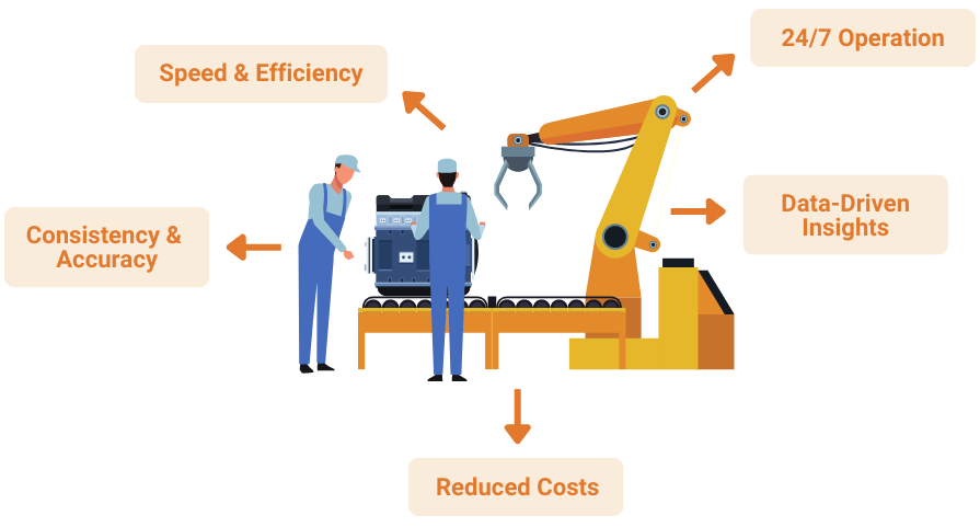
➜ Speed and Efficiency

AVI systems can inspect products at an incredibly high speed, far surpassing the capabilities of manual inspection, leading to faster production cycles.

➜ Consistency and Accuracy

AVI eliminates the variability associated with human judgment, ensuring every product is evaluated against the same standards with unparalleled accuracy.

➜ Reduced Costs

While initial setup costs might be higher, the long-term benefits include reduced waste, fewer recalls, and decreased labor costs due to reduced need for manual inspection.

➜ 24/7 Operation

Automated visual inspection operates around the clock, providing consistent quality control even during non-working hours.

➜ Data-Driven Insights

The data collected from AVI systems can be analyzed to identify trends, patterns, and potential areas for process optimization.

Conclusion

Automated Visual Inspection is a dynamic force reshaping quality control across industries. With its advanced technology, diverse sensors, and real-time insights, AVI empowers businesses to ensure product integrity and exceed consumer expectations. This evolution towards precision, efficiency, and elevated standards signifies not just a transformation in inspection methods, but a reimagining of quality itself.

2024-03-27T17:24:16-07:00Thursday, March 21, 2024|Blog|

Cargo Fire Suppression: A Strong Shield, but is it Enough?

Is Cargo Fire Suppression Enough to Keep You Safe?

Fire Safety in Aviation and Maritime Shipping

In the realm of modern logistics, the secure transportation of goods across skies and seas is paramount for global trade. Yet, in the midst of this complex network of transportation, the looming threat of cargo fires remains a persistent worry. The potential devastation brought by a cargo fire necessitates comprehensive safety measures spanning diverse transit modes.

Both aviation and maritime industries acknowledge the significance of shielding cargo from multifaceted fire risks. Regardless of the mode of transportation, the core objective remains unwavering: preventing and mitigating fire incidents to protect cargo, crew, passengers, and vessels alike.

Amid these challenges, cargo fire suppression systems emerge as crucial safeguards. Tailored for swift detection and containment, they play pivotal roles in curbing fire hazards. However, a holistic safety strategy extends beyond suppression. Early fire detection systems emerge as vital partners, preemptively identifying potential fire threats long before they escalate.

In this article, we unravel the diverse causes of cargo fires, examine the limitations of fire suppression systems, and introduce early detection technologies. Furthermore, we explore the advantages offered by early fire detection systems, highlighting their transformative potential in enhancing cargo safety during transit.

cargo fire suppression industries

Understanding the Origins and Triggers of Cargo Fires

Cargo fires represent a challenge in both aviation and maritime transportation, posing risks not only to the valuable goods being transported but also to the safety of passengers, crew, and vessels. To effectively address this threat, it’s essential to comprehend the underlying causes of cargo fires and the conditions that can lead to their ignition.

Variety of Ignition Sources

Cargo fires can originate from a diverse array of ignition sources. In the aviation industry, electrical malfunctions, particularly those involving batteries, constitute a significant proportion of fire incidents. The proliferation of lithium-ion batteries, widely used to power various devices, poses a heightened risk due to their potential for thermal runaway—a self-perpetuating chain reaction of overheating that can lead to ignition. Similarly, in the maritime domain, electrical faults, machinery failures, and even hazardous cargo interactions can trigger fires.

Combustible Cargo Contents

Another crucial factor contributing to cargo fires is the nature of the transported goods themselves. Various cargoes, including flammable liquids, gases, chemicals, and even certain types of dry goods, can pose fire risks due to their inherent combustibility or potential for spontaneous ignition. Incorrectly packaged dangerous materials can worsen these risks, highlighting the importance of following safety rules and guidelines.

Cargo Compartment Design and Ventilation

The design of cargo compartments, whether within aircraft or ships, plays a pivotal role in fire propagation. Poor ventilation can allow heat and smoke to accumulate, intensifying the fire and making it more challenging for fire suppression systems to effectively combat the blaze. Similarly, cargo stowage configurations can impact the potential for fires to spread, underscoring the importance of proper loading procedures.

Environmental Conditions

Environmental factors, including temperature and humidity fluctuations, can also contribute to fire risks. Inadequate temperature control can cause temperature-sensitive cargoes to become more prone to ignition. Moreover, the maritime environment introduces the added complexity of saltwater exposure, which can corrode electrical systems and potentially lead to short circuits.

Comprehending the multifaceted nature of cargo fires is crucial for devising effective preventive measures. The confluence of ignition sources, cargo contents, compartment design, and external factors underscores the need for a holistic approach to fire safety that encompasses both prevention and rapid response.

The Limitations of Fire Suppression Systems

Fire suppression systems are important for preventing cargo fires, but they have limitations that need to be recognized. The intricacies of fire dynamics, coupled with the complexities of different cargo compositions and transportation environments, can lead to limitations that require careful consideration. Understanding these limitations is crucial for designing a comprehensive cargo safety strategy that effectively addresses potential challenges.

Preventing Metal Recycling Fires with Early Fire Detection

Activation Time and Delay

One of the primary limitations of fire suppression systems lies in the time it takes for the system to activate upon detecting a fire. While these systems are designed for rapid response, even a few seconds of delay can provide a fire with ample opportunity to escalate. Factors such as the location of the fire within the cargo hold, sensor calibration, and activation protocols can impact the system’s effectiveness in containing a blaze before it intensifies.

Potential for Collateral Damage

While suppression agents are invaluable for extinguishing fires, their deployment often carries the risk of collateral damage. For example, the use of foam to smother fires can lead to residue accumulation and potential harm to sensitive cargo items. Striking a balance between swift fire containment and minimizing damage to valuable cargo assets becomes a delicate act that requires careful consideration.

Limited Effectiveness Against Certain Fires

Despite their advancements, fire suppression systems might face challenges when it comes to combating certain types of fires. Fires involving highly reactive chemicals, such as those found in lithium-ion battery packs or industrial materials, can pose formidable obstacles due to their unique ignition mechanisms and the limited efficacy of conventional suppression agents against them.

Incorporating these limitations into the broader understanding of cargo fire safety illuminates the need for a comprehensive approach that combines fire suppression systems with other proactive measures, such as early detection mechanisms and robust safety protocols. By acknowledging and addressing these limitations, aviation and maritime industries can chart a course towards a more secure and reliable transportation of goods across skies and seas.

Enhancing Cargo Safety through Early Fire Detection

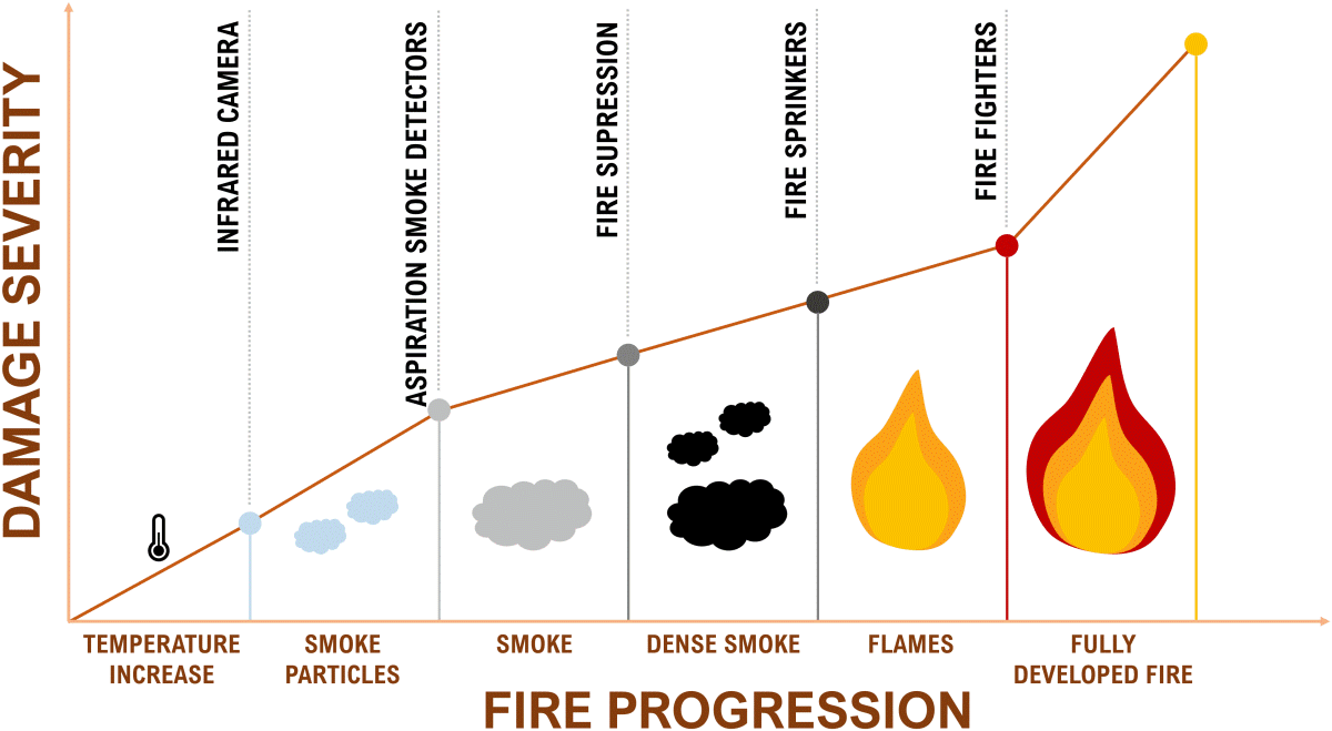
Safety doesn’t solely hinge on reactive measures—it also thrives on the foresight to prevent emergencies before they unfold. Early fire detection systems are an important part of defense against fires, working alongside fire suppression systems.

Early fire detection systems serve as vigilant guardians, equipped to identify the first signs of potential fire hazards before they ignite. Among these advanced technologies, infrared cameras stand out as crucial tools in the pursuit of cargo safety.

Infrared (IR) cameras offer a window into the world of heat, revealing otherwise invisible temperature differences. When anomalies in temperature arise, possibly indicating the presence of a fire, these cameras swiftly capture the thermal signatures. Early fire detection systems trigger alarms and alerts when deviations from the norm are detected. Crew members and operators are promptly informed, enabling them to take immediate action, initiate protocols, and potentially avert a full-scale fire event.

cargo fire suppression but make it early fire detection

Advantages of Early Detection

The advantages presented by early fire detection systems are both substantial and multifaceted, contributing to a holistic approach to cargo safety:

Proactive Prevention

Early detection systems afford the opportunity to intercept fire risks in their initial stage. By alarming at the earliest indications of trouble, these systems allow operators and crew to intervene before a fire even ignites, thwarting potentially catastrophic events.

Reduced Dependency on Suppression

One of the most compelling aspects of early fire detection is its capacity to curtail the necessity for fire suppression measures. By stopping a fire before it becomes unmanageable, these systems reduce the reliance on aggressive suppression agents, which can sometimes lead to collateral damage or asset loss.

Preservation of Valuables

Early fire detection can be particularly instrumental in safeguarding valuable cargo contents. By preventing fires or detecting them in their initial stages, these systems contribute to the preservation of goods and assets, minimizing financial losses and maintaining the integrity of transported items.

A Symbiotic Approach to Safety

The interplay between fire suppression systems and early detection systems underscores the synergy that underpins modern cargo safety strategies. While fire suppression systems respond swiftly to contained fires, early detection systems extend their protective embrace by stopping potential fires in their tracks. Together, they embody a comprehensive approach that maximizes the potential for a safe and secure journey.

early fire detection for cargo

Ready to Elevate Cargo Safety?

Explore the Power of Early Fire Detection Systems Today!

2024-03-27T17:28:04-07:00Thursday, March 21, 2024|Blog|

Power Plant Fire Protection: The Biomass One Success Story

Power Plant Fire Protection Application Story

Biomass One’s Journey to Improving Power Plant Fire Protection

Biomass One, a leading biomass power plant located in White City, Oregon, has continuously pushed the boundaries of the industry by embracing cutting-edge technologies. At the forefront of their mission is the unwavering commitment to enhancing safety and efficiency within their operations. One significant challenge they faced was the prevention of fires in their biomass wood piles, a critical aspect of power plant fire protection.

In this article, we delve into the success story of Biomass One and shed light on the key role played by the Intelligent Early Fire Detection (iEFD) solution provided by MoviTHERM. This innovative solution not only improved the overall safety standards but also emerged as a cost-effective alternative to manual fire watch staff.

Challenges Faced and the Need for an Efficient Solution

Biomass One faced significant challenges when it came to hiring and managing fire watch staff. These challenges resulted in operational disruptions and increased costs for the power plant. To find a more proactive approach, Biomass One turned to a handheld infrared (IR) camera for monitoring their biomass hog fuel piles. While this technology offered some benefits in detecting potential fire hazards, it still relied on manual monitoring by staff, which introduced the possibility of oversight and human error. Recognizing the limitations of these approaches, Biomass One sought a more efficient and reliable solution.

An Efficient and Cost-Effective Alternative

In their quest for a reliable and automated fire detection system, Biomass One turned to MoviTHERM and their innovative iEFD solution. This system provided continuous real-time monitoring of the biomass wood piles, eliminating the need for manual monitoring or dedicated fire watch staff. By detecting hot spots early on, the iEFD system enabled proactive intervention to prevent fires from escalating, bolstering power plant fire protection measures. In addition to enhancing safety, the iEFD solution proved to be a cost-effective alternative to hiring and managing personnel.

Fire Department’s Positive Outlook on MoviTHERM’s iEFD

Prior to purchasing the iEFD solution from MoviTHERM, Biomass One proactively engaged with the local fire department to seek their opinion on the proposed fire detection system. The fire department, being well-versed in fire prevention and detection techniques, quickly recognized the value and effectiveness of the iEFD solution. In fact, they considered it a “no brainer” due to their own use of infrared cameras for fire detection purposes. The fire department’s endorsement further solidified the credibility and reliability of the iEFD solution. Encouraged by this positive feedback and the shared enthusiasm for advanced infrared technology, Biomass One proceeded with confidence and installed the iEFD system, knowing it had the support and trust of the local fire department.

The Successful Implementation of the iEFD Solution

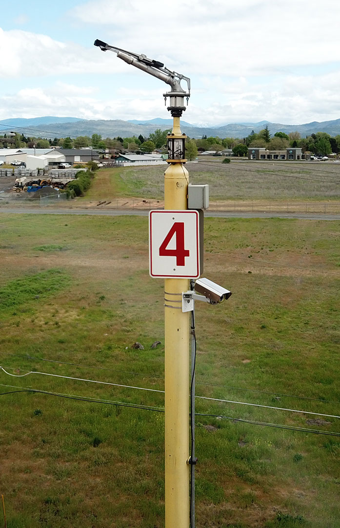
early fire detection camera mounted on pole with water sprinkler, part of their strategic plan for power plant fire protection

Infrared camera and water canon mounted on pole to monitor biomass fuel piles.

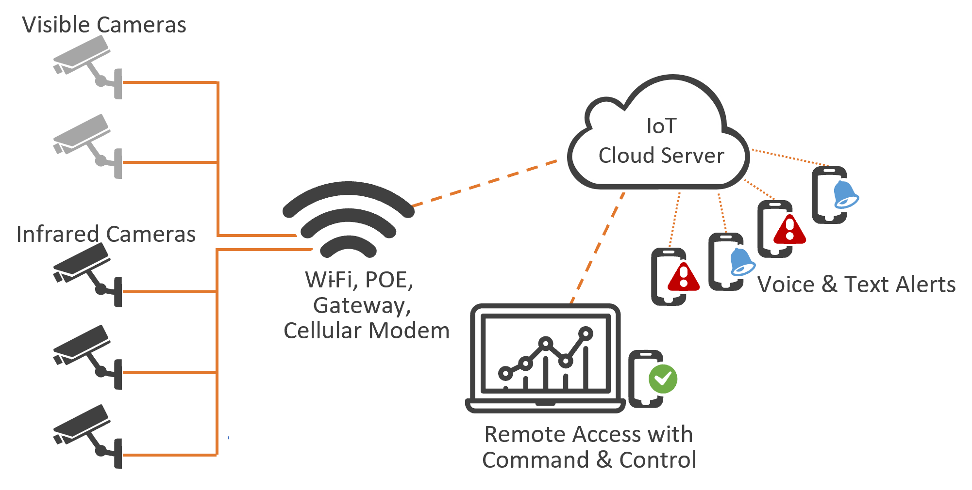
Biomass One went the extra mile to ensure comprehensive safety measures by strategically integrating the iEFD system with their existing infrastructure. In a proactive move, they installed the IR cameras above their existing water cannons, allowing for immediate response in the event of a fire.

If the cameras detect a hot spot, the control room receives real-time alarms and notifications. This immediate alert system ensures that the control room personnel can promptly assess the situation and trigger the necessary actions, including activating the water cannons. The timely response and swift extinguishing of potential fires have helped Biomass One prevent the escalation of incidents and minimize any potential damage or downtime.

Since the implementation of the iEFD solution, Biomass One has experienced remarkable improvements in fire prevention. The continuous real-time monitoring and early detection capabilities of the iEFD system have significantly minimized the risk of fires in their biomass wood piles. As a result, Biomass One has not needed to call the fire department for firefighting operations since the installation of the iEFD system. This stands as a testament to the effectiveness of the solution and showcases the successful collaboration between Biomass One and the fire department.

Conlusion

Biomass One’s successful implementation of MoviTHERM’s iEFD solution revolutionized power plant fire protection, improved safety standards, and strengthened their relationship with the fire department. The collaboration with the fire department prior to installation and their approval of the iEFD system underscored its effectiveness in preventing fires. Since its installation, Biomass One has not required the assistance of the fire department, showcasing the success and reliability of the iEFD solution.

The implementation of proactive fire prevention measures and the enhanced alertness brought by the system have increased peace of mind for the entire team at Biomass One. The iEFD system has provided cost savings and operational efficiency, further enhancing the overall performance of Biomass One. Their experience sets a commendable example for the biomass power generation industry, highlighting the benefits of innovative technologies, collaborative relationships with local authorities, and the implementation of proactive fire prevention measures.

Enhance Your Power Plant’s Fire Protection

Schedule a Call to Learn More About MoviTHERM’s iEFD Solution

2024-03-27T17:26:35-07:00Thursday, March 21, 2024|Blog|

Honeycomb Core Material Inspection of Water Ingress

Inspection of Water Ingress in Honeycomb Core Material

Water ingress in honeycomb core material is a critical issue in aerospace, automotive, and construction industries as it can compromise structural integrity and lead to significant damage over time. Traditional inspection methods, such as visual inspection and ultrasonic testing, have limitations in detecting and characterizing water ingress.

This article explores the application of active thermography, specifically flash thermography and transient thermography, as an effective non-destructive testing (NDT) technique for identifying water ingress in both non-metallic and metallic honeycomb cores. Additionally, we will discuss the advantages of using infrared NDT over ultrasonic testing for this specific application.

Active Thermography for Water Ingress Detection

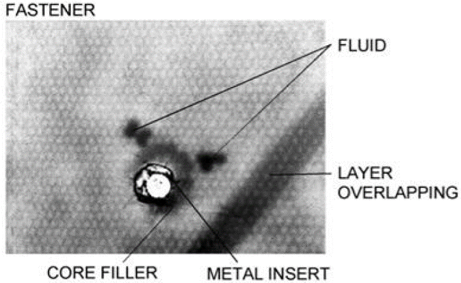
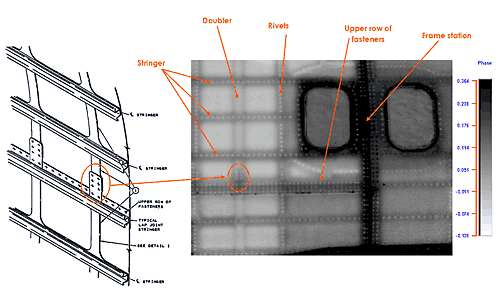
Fastener and fluid ingress.

Flash Thermography

Flash thermography is a widely used active thermography technique that involves subjecting the honeycomb structure to a short-duration, high-energy pulse of heat (e.g., using a flash lamp). As water has different thermal properties compared to the honeycomb material, any water present in the core will affect the way heat is transferred during the inspection process. A high-speed infrared camera captures the surface temperature response, revealing thermal anomalies indicative of water ingress.

Transient Thermography

Transient thermography relies on a continuous heating source, such as an infrared heater or a moving hot air stream, to induce a thermal gradient across the honeycomb structure. Similar to flash thermography, a thermal camera captures the surface temperature response. By analyzing the temperature decay over time, areas with water ingress can be detected and characterized.

Water Ingress Detection in Non-Metallic Honeycomb Cores

Non-metallic honeycomb cores, often composed of materials like aramid fibers or polymers, pose unique challenges for water ingress detection. The presence of water can lead to swelling, delamination, or loss of mechanical properties. Active thermography techniques provide several advantages in this context:

Sensitivity to Water Content

Active thermography can detect even small amounts of water content within non-metallic honeycomb cores. By analyzing the surface temperature response, thermographic images can highlight areas with moisture accumulation, enabling early detection of water ingress and facilitating preventive maintenance.

Enhanced Depth Resolution

Active thermography techniques can provide depth information regarding the location of water ingress. By analyzing the thermal response over time or applying advanced image processing algorithms, it is possible to estimate the depth of water infiltration, aiding in assessing the severity of the damage.

Water Ingress Detection in Metallic Honeycomb Cores

Metallic honeycomb cores, typically composed of materials like aluminum or stainless steel, have different thermal properties compared to non-metallic cores. However, active thermography remains effective for water ingress detection in metallic honeycomb cores, with a few considerations:

Thermal Conductivity Differences

Metallic honeycomb cores have higher thermal conductivities than non-metallic ones. This can result in faster heat transfer during active thermography, potentially affecting the detection sensitivity. Adjustments in the heating and inspection parameters may be required to optimize the water ingress detection process for metallic honeycomb cores.

Subsurface Reflections

Metallic honeycomb cores can produce reflections of thermal energy due to their metallic nature. These reflections can interfere with the detection of water ingress anomalies. Proper image processing techniques, such as advanced filtering algorithms, can be applied to mitigate the impact of these reflections and enhance the detection accuracy.

Advantages of Infrared NDT for Detection of Water Ingress over Ultrasonic Testing

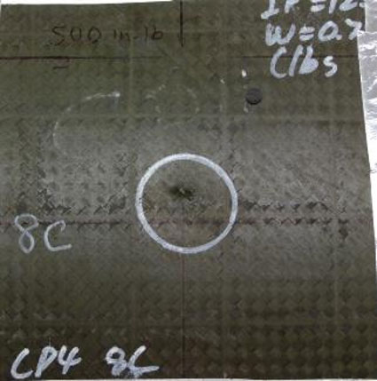
Impact damage and fluid ingress.

Impact damage and fluid ingress.

Surface Accessibility

Ultrasonic testing requires direct contact between the transducer and the surface being inspected. In contrast, infrared NDT is a non-contact technique, allowing inspections to be performed without physically touching the honeycomb structure.

Rapid Inspection

Infrared NDT techniques, such as flash thermography and transient thermography, offer rapid inspection capabilities. The application of short-duration heat pulses or continuous heating sources enables quick scanning of large areas. This is particularly advantageous when inspecting honeycomb structures with complex geometries or when time is a critical factor.

Full-Field Inspection

Infrared NDT provides full-field inspection capabilities, allowing the entire surface of the honeycomb structure to be examined simultaneously. This is in contrast to ultrasonic testing, which typically requires scanning point-by-point, resulting in a time-consuming process. With infrared NDT, potential water ingress areas can be quickly identified, localized, and characterized, enabling efficient decision-making regarding maintenance or repair.

Detection Sensitivity

Active thermography techniques have shown excellent sensitivity to small defects and moisture content variations. The detection of water ingress anomalies, even at early stages, is achievable using high-resolution infrared cameras and appropriate heating methods. Ultrasonic testing, on the other hand, may have limitations in detecting certain types of defects or variations in moisture content.

Thermal result image with fluid ingress indication.

Thermal result image with fluid ingress indication.

Non-Destructive

Infrared NDT is a non-destructive technique that does not alter or damage the honeycomb structure during inspection. This is particularly important for critical applications where the structural integrity of the honeycomb core must be preserved. Ultrasonic testing, while also non-destructive, requires the use of couplant and direct contact with the surface, which can be challenging or impractical in certain scenarios.

Cost-Effectiveness

Infrared NDT techniques offer cost-effective inspection solutions. The equipment required for active thermography, including infrared cameras and heat sources, is becoming more affordable and accessible. Additionally, the rapid inspection capabilities of infrared NDT can reduce labor costs and minimize production downtime, making it a viable option for industries that require efficient and cost-effective inspection processes.

Conclusion

Active thermography techniques, such as flash thermography and transient thermography, provide effective solutions for detecting water ingress in both non-metallic and metallic honeycomb cores. With their sensitivity, depth resolution, and rapid inspection capabilities, active thermography techniques offer advantages over traditional ultrasonic testing methods. Infrared NDT allows for non-contact, full-field inspection, enabling the detection of water ingress anomalies at early stages and facilitating timely maintenance or repair actions. As technology continues to advance, infrared NDT is poised to play an increasingly significant role in ensuring the structural integrity and performance of honeycomb core-based structures in various industries.

Don’t Let Hidden Defects Go Unnoticed

Schedule a call today to learn how you can use active thermography to elevate your inspection process!

2024-03-27T17:30:50-07:00Thursday, March 21, 2024|Blog|

Inspection of Carbon Fiber Structures with Foam Cores

Inspecting Carbon Fiber Structures with Foam Cores

Carbon fiber structures with foam cores are widely used in various industries due to their lightweight and high-strength properties. However, ensuring the structural integrity of these composite materials is crucial, as voids and delaminations can compromise their performance and durability.

In this article, we explore the use of transient and flash thermography as effective non-destructive testing (NDT) techniques for detecting voids and delaminations in carbon fiber structures with foam cores. Additionally, we discuss the significance of foam cores and the problems associated with voids in these structures.

Foam Cores in Carbon Fiber Structures

Foam cores play a vital role in carbon fiber structures, serving as lightweight and insulating materials that provide structural support and enhance the mechanical properties of the composite. They are typically made of materials such as polyurethane or polystyrene and are sandwiched between carbon fiber composite layers. Foam cores offer strength, stiffness, and thermal stability while reducing weight, making them ideal for applications in aerospace, automotive, and marine industries.

Detecting Voids and Delaminations with Transient Thermography

Transient thermography, a dynamic infrared NDT technique, is effective in detecting voids and delaminations in carbon fiber structures with foam cores. The process involves the following steps:

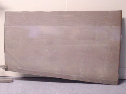
Photo of air foil section with foam core.

Photo of air foil section with foam core.

Heat Pulse Excitation

A controlled heat pulse is applied to the surface of the composite structure using a flash lamp or other heat source. The heat pulse generates a thermal response within the material, inducing changes in temperature and heat flow.

Thermal Imaging and Analysis

An infrared camera captures the surface temperature response during and after the heat pulse. Voids and delaminations within the foam core or between the foam core and carbon fiber layers disrupt the normal heat flow, resulting in distinct thermal patterns. Advanced image processing techniques and algorithms are utilized to analyze thermal images and identify areas with abnormal thermal signatures.

Void and Delamination Identification

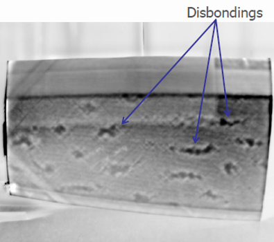
Transient thermography enables the identification of voids and delaminations within carbon fiber structures. Voids appear as areas with reduced heat conductivity or localized temperature variations, while delaminations manifest as irregular heat dissipation or thermal gradients. The size, shape, and location of these thermal anomalies provide valuable information about the extent and severity of the defects.

Flash Thermography for Void and Delamination Detection

Flash thermography, another dynamic infrared NDT technique, can also be employed to detect voids and delaminations in carbon fiber structures with foam cores. The process is similar to transient thermography but involves the use of a shorter heat pulse. Flash thermography offers the advantage of rapid inspection, allowing for efficient scanning of large areas and detecting defects in real-time.

Significance of Void Detection in Carbon Fiber Structures

Voids in carbon fiber structures with foam cores pose significant problems for their performance and structural integrity. The presence of voids leads to several issues:

Thermal result image with voids (disbonds) in Carbon Fiber Structures with Foam Cores

Thermal result image with voids (disbonds) in foam.

Reduced Mechanical Strength

Voids create areas of weakness within the structure, compromising its overall mechanical strength. They act as stress concentration points, leading to premature failure or reduced load-bearing capacity.

Impaired Load Transfer

Voids disrupt the efficient transfer of loads between the carbon fiber layers and the foam core, reducing the structural efficiency of the composite material. This can result in localized stress concentrations and uneven distribution of forces, further compromising the structural integrity.

Moisture Absorption and Degradation

Voids provide pathways for moisture infiltration, leading to the absorption of water and subsequent degradation of the foam core material. Moisture-induced damage can weaken the composite structure and promote corrosion of metal components, further exacerbating structural issues.

Conclusion

Transient and flash thermography offer effective means of detecting voids and delaminations in carbon fiber structures with foam cores. By analyzing thermal responses generated by controlled heat pulses, these non-destructive testing techniques allow for the identification and evaluation of defects. Voids in carbon fiber structures pose significant problems, including reduced mechanical strength, impaired load transfer, and moisture-related degradation. Detecting and addressing voids and delaminations early is essential to ensure the structural integrity and performance of carbon fiber structures with foam cores in various industries.

Don’t Let Hidden Defects Go Unnoticed

Schedule a call today to learn how you can elevate your inspection process with advanced thermography solutions!

2024-03-27T17:33:17-07:00Thursday, March 21, 2024|Blog|

Turbine Blade Inspection Using Vibro-Thermography

Turbine Blade Inspection Using Vibro-Thermography NDT Technique

A Reliable NDT Technique for Detecting Surface and Subsurface Cracks in Turbine Blades

Turbine blade inspection plays a crucial role in aerospace, power generation, and industrial applications, where the structural integrity of these components directly impacts operational efficiency and safety. Detecting cracks in turbine blades is of utmost importance to ensure their reliable performance. Traditional inspection methods, such as dye penetrant testing, have limitations in detecting subsurface cracks.

This article explores the application of vibro-thermography as an effective non-destructive testing (NDT) technique for detecting both surface and subsurface cracks in turbine blades. Additionally, we will discuss the limitations of dye penetrant testing in detecting subsurface cracks and the reasons behind them.

Table of Contents

Challenges with Traditional Inspection Methods

Limitations of Dye Penetrant Testing

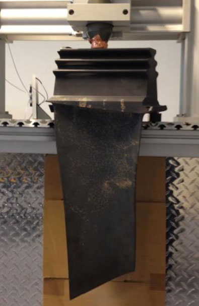
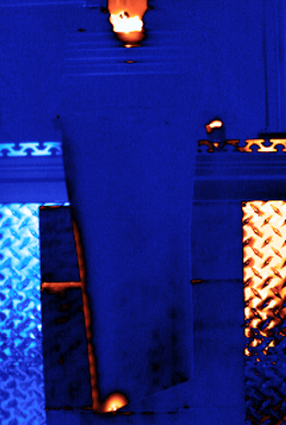
Large turbine blade with ultrasonic horn in test fixture.

Large turbine blade with ultrasonic horn in test fixture.

Dye penetrant testing, a commonly used method for crack detection, primarily focuses on surface-breaking cracks. However, it has inherent limitations when it comes to detecting subsurface cracks in turbine blades. The nature of subsurface cracks makes it challenging for liquid penetrants to reach the crack depths, resulting in limited or no indication of their presence. Additionally, visual examination is often insufficient for identifying subsurface cracks, especially when they are located deep within the material.

Insufficient Crack Visualization

Surface examinations alone may not provide an accurate representation of the extent and severity of turbine blade cracks. Without clear visualization, it becomes challenging to characterize cracks in terms of size, depth, and extent, hindering effective maintenance and repair decisions.

Vibro-Thermography for Turbine Blade Inspection

To overcome the limitations of traditional inspection methods, advanced techniques like vibro-thermography have emerged as promising solutions for more comprehensive turbine blade inspections.

How Vibro-Thermography Works

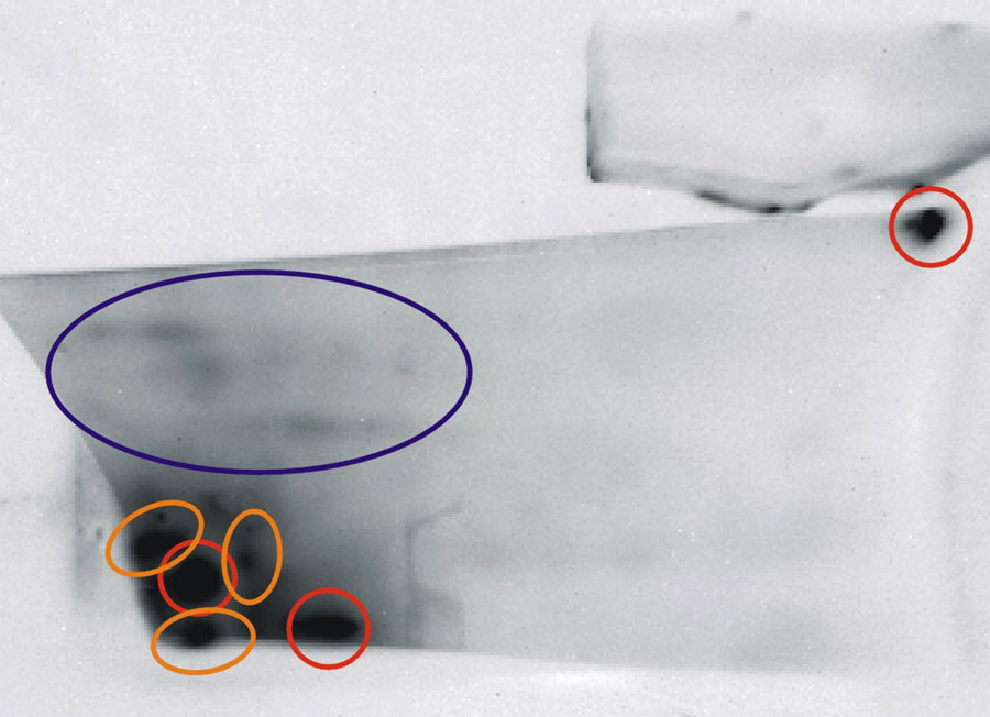
Thermal result image with large crack indication on bottom edge of blade.

Thermal result image with large crack indication on bottom edge of blade.

Vibro-thermography combines the principles of vibration excitation and thermal imaging to detect cracks in turbine blades. The technique involves inducing mechanical vibrations into the blade and monitoring the surface temperature response using an infrared camera. By analyzing the thermal patterns, it is possible to identify both surface and subsurface cracks.

Vibration Excitation

Vibro-thermography utilizes various methods to induce vibrations in turbine blades. These include mechanical excitation using shakers, air-coupled excitation, or piezoelectric actuators. The vibrations cause dynamic stress redistribution, leading to localized heating at crack sites. This phenomenon enables the detection of subsurface cracks that may not be visible to the naked eye.

Thermal Imaging

An infrared camera captures the surface temperature response of the turbine blade during vibration excitation. Subsurface cracks disrupt heat flow, resulting in thermal anomalies that can be visualized and analyzed. Advanced image processing techniques can enhance crack visibility and aid in quantitative characterization, providing valuable insights for maintenance and repair decisions.

Advantages of Vibro-Thermography for Turbine Blade Inspection

Subsurface Crack Detection

Vibro-thermography excels in detecting subsurface cracks in turbine blades. By inducing vibrations and monitoring the resulting thermal patterns, the technique can identify cracks even when they are not visible on the surface. This capability enables comprehensive inspection, ensuring the integrity of turbine blades, even in critical areas prone to subsurface cracking.

Enhanced Crack Visualization

Thermal results image - front view of turbine blade with crack indications.

Thermal results image – front view of turbine blade with crack indications.

The thermal imaging component of vibro-thermography provides a visual representation of cracks, making them easier to identify and characterize. The contrast between crack-induced thermal anomalies and the surrounding material facilitates accurate detection and quantification of crack size, depth, and extent. This information allows maintenance teams to make informed decisions regarding repairs or replacements.

Non-Destructive Testing

Vibro-thermography is a non-destructive testing technique that does not alter or damage the turbine blade during inspection. The vibrations applied are controlled and within safe limits, allowing for repeated inspections without compromising the structural integrity of the blade. This advantage is particularly significant in critical applications where turbine blade performance is crucial.

Turbine blade rear view with sub-surface micro-cracking indications.

Turbine blade rear view with sub-surface micro-cracking indications.

Time-Efficient Inspection

Vibro-thermography offers a time-efficient inspection process, allowing for rapid scanning of turbine blades. The application of controlled vibrations and the real-time monitoring of thermal responses enable quick assessment of the blade’s condition. This time-saving advantage is particularly valuable in industries where minimizing downtime is essential.

Emerging Trends in Vibro-Thermography

As technology continues to advance, new trends and developments are emerging in the field of vibro-thermography, enhancing its capabilities and expanding its applications. Here are some notable trends to watch out for:

Multi-Frequency Excitation

Traditional vibro-thermography techniques rely on single-frequency excitation to induce vibrations in turbine blades. However, researchers are exploring the benefits of multi-frequency excitation, where multiple vibration frequencies are applied simultaneously. This approach can provide more detailed information about the structural integrity of the blades, improving crack detection accuracy and reducing false positives.

Integration of Artificial Intelligence

The integration of artificial intelligence (AI) techniques with vibro-thermography is gaining traction. AI algorithms can analyze the thermal response data collected during inspections, enabling automated crack detection and characterization. Machine learning algorithms can learn from past inspection data to improve the accuracy and efficiency of future inspections, making the process even more reliable and cost-effective.

Real-Time Monitoring

Real-time monitoring during vibro-thermography inspections is becoming increasingly important. By continuously monitoring the thermal response of turbine blades as vibrations are applied, potential defects or changes in crack behavior can be identified promptly. Real-time monitoring enables proactive maintenance and repair decisions, minimizing the risk of unexpected failures and maximizing the lifespan of turbine blades.

Portable and Handheld Systems

With advancements in sensor technology and miniaturization, portable and handheld vibro-thermography systems are becoming more accessible. These compact systems allow for on-site inspections and can be easily transported to different locations. Portable systems offer convenience and flexibility, particularly in situations where transporting large equipment is challenging or time-consuming.

Interested in Implementing Vibro-Thermography for Your Inspections?

If you’re looking to optimize your inspection processes and enhance the reliability of crack detection in turbine blades or other critical components, we can help. MoviTHERM offers state-of-the-art vibro-thermography systems that can revolutionize your inspection capabilities.

Our experienced team can assess your specific needs and provide tailored solutions to meet your requirements. Whether you operate in the aerospace, power generation, or industrial sector, vibro-thermography can offer significant advantages in ensuring the integrity and safety of your parts.

Contact us today to schedule a consultation and find out how our systems can help you detect and characterize cracks in your turbine blades or other critical components.

Don’t Let Hidden Cracks Go Unnoticed

Schedule a call today to learn how you can elevate your inspection process with vibro-thermography!

2024-03-27T17:35:16-07:00Thursday, March 21, 2024|Blog|

Delamination Inspection in CFRP Structures

Delamination Inspection in CFRP Structures Using Infrared

Enhancing CFRP Stringer Integrity with Transient Thermography

Delamination inspection plays a crucial role in assessing the structural integrity of composite materials. Carbon fiber reinforced plastic (CFRP) structures, widely used in aerospace, automotive, and other industries, rely on strong bond lines between components for structural integrity. Detecting defects, such as inadequate bonding or delamination, is crucial to ensure the reliable performance of CFRP structures.

Infrared nondestructive testing (NDT), specifically transient thermography, provides an effective means of inspecting bond lines and identifying delaminated areas. This article explores how transient thermography can be utilized for inspecting bond lines in CFRP stringers, discussing its ability to measure bond strength and identify delaminated regions.

Table of Contents

Transient Thermography for Bond Line Inspection

Transient thermography, a dynamic infrared NDT technique, involves applying a localized heat pulse to the surface of the CFRP structure and monitoring the resulting temperature changes using an infrared camera. The recorded thermal response provides valuable information about the bond line integrity and delamination within the stringer.

Heat Pulse Excitation

irNDT Analysis

A controlled heat pulse is applied to the surface of the CFRP stringer. This excitation generates a thermal gradient, causing heat to flow through the structure and interact with the bond lines. Areas with anomalies, such as poor bonding or delamination, disrupt the heat flow and result in distinct thermal patterns.

Thermal Imaging and Analysis

An infrared camera captures the surface temperature response during and after the heat pulse. The thermal images are analyzed to identify variations in heat dissipation, indicating potential defects in the bond lines. Advanced image processing techniques, such as time-temperature curve analysis or phase-based thermographic analysis, can be employed to enhance defect visibility and accurately assess bond line conditions.

Measuring Bond Strength

Transient thermography offers the capability to measure bond strength in CFRP stringers by assessing the thermal characteristics of the bond lines. Measuring bond strength is essential for evaluating the structural integrity and reliability of composite materials. By analyzing the thermal response and employing advanced testing methods, several factors can be considered to accurately assess bond strength.

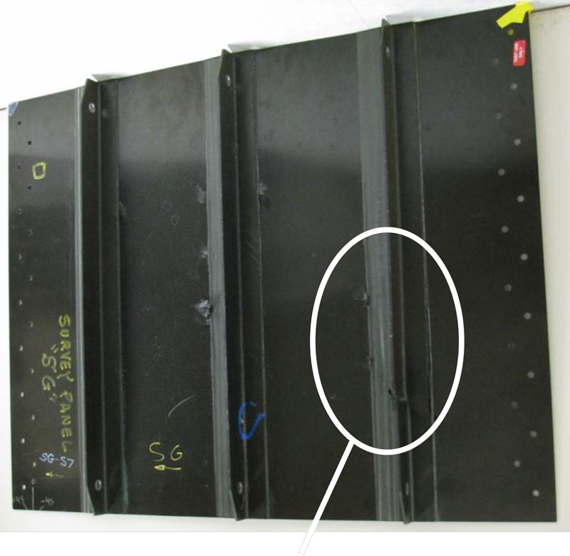
Photo of CFRP panel with partially delaminated stringers.

Thermal Conductivity Differences

The bond line area exhibits different thermal conductivity compared to the surrounding CFRP material. This discrepancy in thermal properties affects heat transfer during transient thermography. By carefully analyzing the thermal response, including temperature profiles and thermal gradients, it is possible to estimate the bond strength based on the bond line’s ability to transmit heat. Understanding the relationship between thermal behavior and bond strength provides valuable insights into the quality and effectiveness of the bonding process.

Quantitative Assessment

To determine bond strength, quantitative analysis of the thermal response is crucial. By comparing the temperature profiles and gradients in regions with known bonding conditions, a correlation can be established between thermal behavior and bond strength. This correlation can be further refined through calibration using reference samples with known bond strengths. Through this quantitative assessment, it becomes possible to assign numerical values to bond strength, enabling a more precise evaluation of the structural integrity of CFRP stringers.

Influence of Manufacturing Variables

It is important to consider various manufacturing variables that can impact bond strength. Factors such as surface preparation, adhesive type, curing conditions, and application techniques play a significant role in determining the strength of the bond line. By understanding the influence of these variables on the thermal response, it becomes possible to assess the bond strength accurately. This knowledge also allows for optimization of the manufacturing process to ensure consistent and robust bonding in CFRP structures.

Long-Term Bond Performance

Transient thermography not only enables the measurement of bond strength during initial inspection but can also provide insights into the long-term performance of the bond line. Over time, environmental conditions, cyclic loading, and other factors can affect the bond strength. By periodically conducting transient thermography inspections, changes in the thermal response can be monitored, allowing for early detection of potential degradation or delamination. This proactive approach helps to ensure the ongoing structural integrity of CFRP stringers and facilitates timely maintenance or repair actions.

Detecting Delaminated Areas

Transient result image showing bond line and partial delamination.

Transient thermography is highly effective in detecting delaminated areas within CFRP stringers. Delamination refers to the separation of layers within the composite structure, compromising its strength and integrity. Key considerations for delamination detection include:

Heat Flow Disruption

Delamination disrupts the normal heat flow within the CFRP structure, resulting in distinct thermal anomalies. During transient thermography, the presence of delamination manifests as areas with slower heat dissipation or abnormal thermal gradients. These thermal patterns are easily detectable in the captured infrared images.

Depth Assessment

Transient thermography can provide valuable information about the depth and extent of delamination. By analyzing the thermal response over time and employing advanced image processing algorithms, the depth of the delaminated region can be estimated. This information helps in assessing the severity of the defect and determining appropriate repair or maintenance actions.

Advantages of Transient Thermography for CFRP Stringer Inspection

Transient thermography offers a range of advantages when it comes to inspecting bond lines and detecting delaminated areas in CFRP stringers. These advantages make it a valuable tool for ensuring the structural reliability of CFRP structures across various industries. Let’s explore some of the key benefits of using transient thermography:

Non-Destructive and Non-Contact Inspectionirndt graphic

One of the primary advantages of transient thermography is its non-destructive and non-contact nature. It allows for the assessment of CFRP stringers without causing any damage to the structure. This means that inspections can be repeated multiple times without compromising the integrity of the component. Non-destructive and non-contact inspection methods are essential for ensuring the longevity and usability of CFRP structures.

Rapid Inspection

Transient thermography offers rapid inspection capabilities, enabling the scanning of large areas in a relatively short amount of time. The application of controlled heat pulses and real-time thermal imaging allows for efficient detection and characterization of bond line defects and delaminated areas. This speed and efficiency are particularly advantageous when inspecting large structures or when time is a critical factor, minimizing production or maintenance downtime.

Full-Field Inspection

Infrared NDT techniques, such as transient thermography, provide full-field inspection capabilities. The entire surface of the CFRP stringer can be examined simultaneously, providing comprehensive information about the bond lines and delamination across the structure. This advantage minimizes the risk of missing critical defects and ensures thorough inspection coverage. Full-field inspection is particularly beneficial for identifying localized anomalies or irregularities that may not be apparent through other inspection methods.

High Sensitivity to Defects

Transient thermography exhibits high sensitivity to defects, including delamination and bond line irregularities. The thermal imaging technique can capture even subtle variations in heat dissipation, enabling the detection of hidden or sub-surface defects that may not be visible to the naked eye. This sensitivity ensures that potential issues are identified early, allowing for timely repairs or interventions to prevent further damage or structural failures.

Versatility and Adaptability

Transient thermography is a versatile inspection method that can be applied to various types of CFRP structures and configurations. It can be used for both flat and curved surfaces, making it suitable for a wide range of applications. The technique can also be adapted to different inspection scenarios and can be combined with other non-destructive testing methods to provide a more comprehensive assessment of the CFRP stringers.

Conclusion

Transient thermography offers a reliable and efficient method for inspecting bond lines and detecting delaminated areas in CFRP stringers. By utilizing heat pulse excitation and analyzing the resulting thermal response, this infrared NDT technique provides valuable insights into bond line integrity and the presence of delamination. The ability to measure bond strength and assess delamination depth, along with its non-destructive and rapid inspection capabilities, makes transient thermography a valuable tool for ensuring the structural reliability of CFRP stringers in various industries.

Enhance Your CFRP Inspection

Contact us today to learn more about our transient thermography solutions!

2024-03-27T17:43:16-07:00Thursday, March 21, 2024|Blog|

Unveiling Corrosion Under Paint with Flash Thermography

Detecting Corrosion Under Paint with Flash Thermography

Corrosion under paint is a pervasive issue that affects various industries, leading to structural integrity problems and costly damage. Detecting corrosion early is essential for effective maintenance and prevention. Flash thermography, a non-destructive testing (NDT) technique, offers a reliable method for detecting corrosion hidden underneath paint layers.

This article explores the application of flash thermography in identifying hidden corrosion, discusses the causes and consequences of corrosion under paint, and explains the process of accelerated corrosion testing using saltwater spray. Additionally, we will clarify the difference between rust and corrosion.

Understanding Corrosion Under Paint

Corrosion is the deterioration of metals caused by electrochemical reactions with the surrounding environment. When metals are coated with paint, corrosion can occur beneath the paint layer, remaining unseen and challenging to detect.

Differentiating Rust and Corrosion

Rust is a specific type of corrosion that occurs when iron or steel reacts with oxygen and moisture, forming iron oxide (Fe2O3). Corrosion, on the other hand, is a broader term encompassing the deterioration of various metals due to chemical reactions with their environment. While rust is a common form of corrosion, other metals can corrode in different ways, depending on their composition and exposure conditions.

corrosion under paint thermal image result

Thermal Image Result of Corrosion Under Paint

Causes and Consequences of Corrosion Under Paint

Corrosion under paint can result from factors such as moisture infiltration, exposure to corrosive gases or chemicals, and inadequate surface preparation before painting. Moisture plays a critical role in corrosion by facilitating the formation of electrolytes necessary for electrochemical reactions. Corrosion under paint compromises the structural integrity of metal components, leading to reduced performance, safety risks, and costly repairs or replacements.

Flash Thermography for Corrosion Detection

Flash thermography, an NDT technique, utilizes short-duration heat pulses to identify thermal anomalies associated with corrosion beneath paint. The process involves the following steps:

Heat Pulse Application

A high-intensity heat pulse is applied to the painted metal surface using a flash lamp or controlled heating source. The rapid heating induces thermal responses within the material.

Thermal Imaging and Analysis

An infrared camera captures the surface temperature response during and after the heat pulse. Areas with corrosion or delamination beneath the paint exhibit different thermal properties, resulting in distinct thermal patterns. Image processing algorithms and analysis techniques enhance the visibility and interpretation of these thermal anomalies.

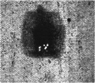
Flash Thermography Metal Sample with Corrosion

Flash Thermography Metal Sample with Corrosion

Identifying Corrosion

Thermal anomalies detected by flash thermography indicate potential areas of corrosion beneath the paint. These anomalies may manifest as localized temperature variations, irregular heat dissipation, or abnormal thermal gradients. The size, shape, and distribution of the thermal anomalies provide valuable information for evaluating the extent and severity of corrosion.

Accelerated Corrosion Testing with Salt Water Spray

To simulate and accelerate the effects of corrosion, companies often perform accelerated corrosion tests using salt water spray. This test involves the following steps:

Test Setup

Metal specimens or coated components are exposed to a controlled environment where a fine mist of salt water is continuously sprayed onto the surface. The salt water spray contains a high concentration of sodium chloride (NaCl) and other corrosive agents.

Corrosion Progression

The specimens are subjected to prolonged exposure to the salt water spray, simulating the corrosive conditions experienced in real-world environments over an extended period. This accelerated exposure speeds up the corrosion process, enabling quicker evaluation of material performance and coating durability.

Evaluation and Analysis

At regular intervals, the specimens are visually examined or assessed using NDT techniques like flash thermography to determine the extent of corrosion and detect any coating failures. The test results provide valuable data on the effectiveness of protective coatings and materials in preventing corrosion.

Conclusion

Flash thermography is a reliable method for detecting hidden corrosion beneath paint layers. By utilizing heat pulse excitation and analyzing the resulting thermal response, flash thermography enables the identification of concealed corrosion. It offers a valuable tool for industries to detect corrosion early and take preventive measures. Additionally, accelerated corrosion testing using salt water spray provides a means to assess the durability of coatings and materials in simulated corrosive environments.

Understanding the difference between rust and corrosion helps clarify the various forms of metal deterioration and highlights the importance of comprehensive corrosion detection and prevention strategies for maintaining the integrity of structures and equipment.

Ready to uncover hidden corrosion?

Contact us today to learn how you can enhance your inspection process using our advanced thermography systems!

2024-03-27T17:47:10-07:00Thursday, March 21, 2024|Blog|

Title

Go to Top