MoviTHERM

How to set up the IP address on the MoviTHERM MIO

Set up the IP Address on the MoviTHERM MIO

This video shows you how to set the device IP address on your MoviTHERM MIO.

The MoviTHERM MIO Series – Intelligent I/O Module for FLIR® Cameras – supporting one of the following Camera models: FLIR AX8, FLIR FC Series R or FLIR A310

Remote Monitoring Applications Made Simple

More info about the MoviTHERM MIO Series Intelligent I/O Modules

Before we get started, there is one thing to keep in mind: If you change the MIO’s IP address, just remember that any cameras connected to your MIO network must be on the same subnet as the MIO. So, that means if you change the MIO subnet, you may also need to update the camera IP addresses accordingly.

Ok, let’s get started. First, we need to open a browser window and log into your MIO. So, let’s launch the Google Chrome browser, key in the default MIO IP address, which is 192.168.1.2, and then log in to the MIO. The default MIO password is “password” so let’s type that in and open the Device Settings page.

The Device IP Address field is located toward the bottom of the settings page, under the Network Configuration heading. Just key in the new IP address (and Subnet mask if necessary), then click, “Save Settings and Reboot”.

After the MIO reboots, we can log-in again to verify the change. And there it is!

That’s all you need to do to set the IP address on your MoviTHERM MIO!

Thanks for watching, and remember to view the other how-to videos in this series for additional tips on setting up your MIO system!

2024-03-28T15:28:41-07:00Thursday, March 21, 2024|Knowledgebase|

How to set up a digital output on the MoviTHERM MIO

Set up a Digital Output on the MoviTHERM MIO

This video shows you how to set up a digital output channel on the MoviTHERM MIO.

The MoviTHERM MIO Series – Intelligent I/O Module for FLIR® Cameras – supporting one of the following Camera models: FLIR AX8, FLIR FC Series R or FLIR A310

Remote Monitoring Applications Made Simple

More info about the MoviTHERM MIO Series Intelligent I/O Modules

We start with the assumption that you have already set up an inspection region in your camera. If you haven’t configured your camera yet, other videos in this series can help get you started. Please view them and set up your camera first before watching this video.

Ok, now that you have an inspection region set up in your camera, the first step is to open a browser window and log into your MIO. We will launch the Google Chrome browser, key in the default MIO IP address, which is 192.168.1.2, and log in to the MIO. The default MIO password is “password” so let’s type that in and get started.

Once we have logged in, we want to select the “Script Commands” tab. Click on the tab, and select a command for digital channel 0. We want to set an alarm based on the maximum temperature of an inspection region, so we will select the “Box Max Temperature” option, and then map ROI 1 to the Channel zero output. Next, we need to set the temperature limit for the alarm. We set a temperature limit of 30 degrees Celsius, and save the configuration to store and activate the alarm.

If we jump over to the Debug Page, we can see that our alarm is now responding and setting the Channel 0 output as expected.

That’s all you need to do to configure a digital output channel on the MoviTHERM MIO.

View the other how-to videos in this series for additional tips on setting up your MIO system!
2024-03-28T15:29:15-07:00Thursday, March 21, 2024|Knowledgebase|

How to set the device name on the MoviTHERM MIO

Set Device Name on the MoviTHERM MIO

This video shows you how to set the device name on your MoviTHERM MIO.

The MoviTHERM MIO Series – Intelligent I/O Module for FLIR® Cameras – supporting one of the following Camera models: FLIR AX8, FLIR FC Series R or FLIR A310

Remote Monitoring Applications Made Simple

More info about the MoviTHERM MIO Series Intelligent I/O Modules

The first step is to open a browser window and log into your MIO. We will launch the Google Chrome browser, key in the default MIO IP address, which is 192.168.1.2, and then log in to the MIO. The default MIO password is “password” so let’s type that in and get started.

The Device Name field can be found on the Device Settings tab, which is the tab you will see after logging in.

You can find the editing field under the Device Information heading. Just key the new name of your choice into the text field, then click, “Save Settings and Reboot”.

The Device Name can be very useful if you are accessing multiple MIO units from a single PC.

After the MIO reboots, we can log-in again to verify the change. And there it is!

That’s all you need to do to set the device name on your MoviTHERM MIO!

View the other how-to videos in this series for additional tips on setting up your MIO system!
2024-03-28T15:30:51-07:00Thursday, March 21, 2024|Knowledgebase|

How to set up a 4-20mA output on the MoviTHERM MIO

Set Up a 4-20mA Output on the MoviTHERM MIO

This video shows you how to set up a 4 to 20mA analog output channel on the MoviTHERM MIO.

The MoviTHERM MIO Series – Intelligent I/O Module for FLIR® Cameras – supporting one of the following Camera models: FLIR AX8, FLIR FC Series R or FLIR A310

Remote Monitoring Applications Made Simple

More info about the MoviTHERM MIO Series Intelligent I/O Modules

We start with the assumption that you have already set up an inspection region in your camera. If you haven’t configured your camera yet, other videos in this series can help get you started. Please view them and set up your camera first before continuing with this video.

Ok, now that you have an inspection region set up in your camera, the first step is to open a browser window and log into your MIO. We will launch the Google Chrome browser, key in the default MIO IP address, which is 192.168.1.2, and log in to the MIO. The default MIO password is “password” so let’s type that in and get started.

Once we have logged in, we want to select the “Script Commands” tab. Click on the tab, and select a command for analog channel 0. We want to map the maximum temperature of an inspection region to the channel 0, 4 to 20mA output. We start by selecting the “Box Max Temperature” option, and then select ROI 1 for the Channel 0 output. Next, we need to set the temperature range mapping. We set the temperature scale limits to the range limits of our camera — in this case, -20 to 120 degrees Celsius, based on the low temperature range of our A310 camera. Next, we save the configuration to activate the 4 to 20mA output.

If we jump over to the Debug Page, we can see that our 4 to 20 mA output is now responding and is updating the Channel 0 output as expected across the 4 to 20mA range.

That’s all you need to do to configure an analog output channel on the MoviTHERM MIO.

View the other how-to videos in this series for additional tips on setting up your MIO system!
2024-03-28T15:31:20-07:00Thursday, March 21, 2024|Knowledgebase|

How to set up an inspection region on a FLIR A310 camera

Set up an Inspection Region on a FLIR A310 Camera

This video shows you how to set up an Inspection Region on your FLIR A310 camera.

The MoviTHERM MIO Series – Intelligent I/O Module for FLIR® Cameras – supporting one of the following Camera models: FLIR AX8, FLIR FC Series R or FLIR A310

Remote Monitoring Applications Made Simple

More info about the MoviTHERM MIO Series Intelligent I/O Modules

Before you can use the MIO to detect and respond to temperatures, you first need to set up an inspection area or “region of interest” in the image. This video shows you how to set up that “region or interest” (or ROI) using the FLIR IR Monitor software. But before we can move on with this video, be sure to confirm that:

1) you have FLIR IR Monitor software installed on your PC, and

2) your A310 camera is able to communicate with your PC over an Ethernet connection

If you are not familar with the FLIR IR Monitor software, you can find the installation files on a disk that ships with the A310 camera. If you are unsure about how to assign an IP address to your A310, please refer to the video in this series devoted specifically to setting the A310’s IP address.

Ok, if you have IR Monitor software installed and are communicating with your camera over Ethernet, you are ready to go. The first step is to launch the FLIR IR Monitor application. If this is the first time running the software, you will need to start by selecting the camera. Click in the IR Monitor window to open the Camera Selection Dialog. All connected cameras will appear in the “Available Cameras” pane on the left. (If you have multiple cameras connected, you should see all of the cameras in the “Available Camera” list.)

Select the camera you would like to configure, then click and drag it to the “Camera Grid” region on the right. Next, click “View Cameras in grid” to exit the dialog and switch to the live camera view.

In the Live View mode, you should see a thermal image on the left, and various controls on the right. Let’s go ahead and change to color palette mapping to the Ironbow palette to enhance the visualization. Pull down the Palette control and select “Iron”.

Next, we need to focus the camera. Proper focus is just as important when using thermal cameras, because a fuzzy, out-of-focus thermal image will not report temperatures accurately. Autofocus is often all you need, so try this first. If the autofocus image isn’t as sharp as you like, you can manually fine-tune the focus with the “Near” and “Far” buttons.

When you are satisfied with the focus, click the Analysis tab to get to the Region set-up tools. By default, the camera has one “Spot” region defined. The MIO can monitor “Spot” regions, but for this example want to monitor an Area region. So let’s start by switching OFF the Spot1 region. Click “Spot 1” in the list, and click “Edit” to open the region editing dialog. Uncheck the “Show Spotmeter” parameter and click “Apply” to switch off the Spotmeter, and “OK” to exit.

Next, we want to set up Area 1 as our region of interest or “ROI”. Select “Area 1” and click “Edit”. Check the “Show Area” parameters to enable the new region. If you want to overlay the Maximum and Minimium temperatures from the region over the image, select “Both” from the “Show Max/Min” pulldown menu. Click “Apply” to enable the overlay region in the image.

You can use the “Position” and “Size” parameters to fine-tune the size and position of the region. Click “Apply” to update the overlay as you go. When you are satisfied with the region, click OK to close the dialog box. You can now see the region overlay on the image, along with the hotest and coldest points in the region.

Close IR Monitor to exit. Now you are ready to configure the MIO to respond to temperature changes in the region you have defined. That’s all you need to do to setup a Region of Interest on your FLIR A310 camera!

For more information on how to configure the MIO to work with this region, refer to other videos in this series. The videos about how to set up a 4-20mA Temperature Range output and how to setup a Digital Output Alarm demonstrate the steps.

View the other how-to videos in this series for additional tips on setting up your MIO system!
2024-03-28T15:31:46-07:00Thursday, March 21, 2024|Knowledgebase|

How to set up the IP address on a FLIR A310 camera

Set up the IP Address on a FLIR A310 Camera

This video shows you how to set up the IP address on your FLIR A310 camera.

The MoviTHERM MIO Series – Intelligent I/O Module for FLIR® Cameras – supporting one of the following Camera models: FLIR AX8, FLIR FC Series R or FLIR A310

Remote Monitoring Applications Made Simple

More info about the MoviTHERM MIO Series Intelligent I/O Modules

When setting up your MIO network the camera or cameras on the network must have static IP addresses. They also must reside in the same subnet as the MIO.

The MIOs default IP address is 192.168.1.2. So, if we assign the camera IP addresses in the 192.168.1.XXX subnet.

For the purposes of this video we will assign a static IP address of 192.168.1.111 to our FLIR A310 camera so that it can communicate with our MIO.

Our PCs IP address has already been set to 192.168.1.1. This will permit us to connect the pc to both, the MIO and the A310 camera after the IP addresses have been correctly configured.

Let’s start by launching FLIR IP Config. By default, the A310 camera is typically configured to obtain IP address automatically. We need to set a fixed or static IP address.

Using FLIR IP Config we can select the camera from the connected cameras list and then assign the IP address in the pop-up dialog provided.

Set the radio button to specify a fixed IP address and then fill in the target IP address subnet mask and default gateway in the fields provided. We want to assign the address of 192.168.1.111 to the camera so we will enter the IP address and subnet mask accordingly.

We also need to define default gateway field so we will enter that as well. Click the enter button to activate the changes. A warning dialog pops up to ask if you’re sure. Verify your settings and click OK.

After a moment ipconfig locates the camera at the newly assigned IP address. That’s all you need to do to set the IP address on your FLIR A310 camera.

Be sure to view the other how to videos in this series for additional tips from setting up your MIO System.

2024-03-28T15:32:22-07:00Thursday, March 21, 2024|Knowledgebase|

How to connect a FLIR FC-Series R camera to the MoviTHERM MIO

Connecting a FLIR FC-Series R Camera to the MoviTHERM MIO

In this video, we show how to configure the MoviTHERM MIO-FCR-1 and the FLIR FC-Series R thermal camera. Topics include setting ROIs, connecting the camera and MoviTHERM MIO-FCR-1, and how to assign alarms to the analog and digital outputs in the MoviTHERM MIO module.

The MoviTHERM MIO Series – Intelligent I/O Module for FLIR® Cameras – supporting one of the following Camera models: FLIR AX8, FLIR FC Series R or FLIR A310

Remote Monitoring Applications Made Simple

More info about the MoviTHERM MIO Series Intelligent I/O Modules


2024-03-28T15:32:48-07:00Thursday, March 21, 2024|Knowledgebase|

How to grab an image from a FLIR A35 A65 using LabVIEW

Grab an Image from a FLIR A35 A65 Using LabVIEW

How to grab an image and display the absolute temperature from the thermal camera FLIR A35 A65 using LabVIEW from National Instruments.

The following instructions are intended to provide some beginner level advice and it is a “Hello World” example and a first step in how to capture a thermal image from a FLIR A35 A65 using LabView. The FLIR A35 A65 has a Gigabit Ethernet interface and supports the world-wide machine vision standard GeniCAM. This example actually works for the whole FLIR Ax5 Series.

Download the source code: FLIR_A35_A65_using_LabVIEW.zip (219 KB)

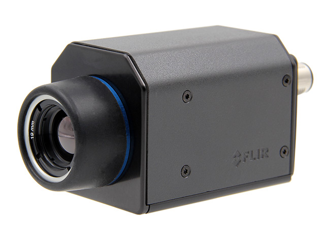
FLIR A65

Here is what you will need for this to work:

  • A PC with a LabVIEW development environment installed.
    • LabVIEW 2015 or later
    • NI Vision Development Module 2015 or later
    • IMAQdx 15.5 or later
  • FLIR A35 or FLIR A65 Thermal Camera connected to PC via Ethernet Cable
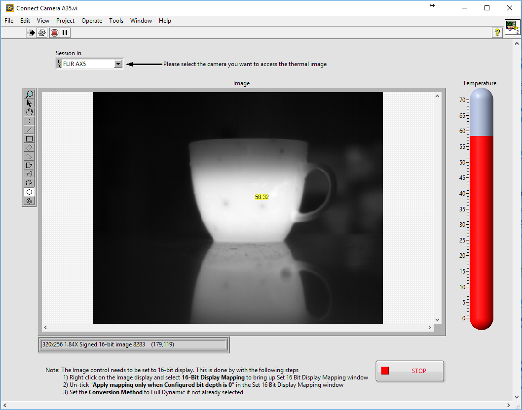
FrontPanel FLIR A35 A65 using LabVIEW

The above is a screenshot of the LabVIEW front panel. In the center is the image display, showing a black and white thermal image of a coffee mug. The brighter the intensity, the higher the temperature. The mouse cursor was placed in the center of the cup. The temperature is superimposed onto the image. The outside of the coffee mug is 64.46 degrees Celsius in this example. Also noticeable is that the image of the mug creates a reflection on the table surface. The surface is reflective in the long wave thermal band that the camera is sensitive to (8 to 14µm).

When you run the VI, it will connect to the camera. This assumes that the camera’s IP address and subnet mask matches the PC’s settings. Instructions on how to do this would go beyond the scope of this example. Once connected, you should see a thermal image after a few seconds. When you hover your mouse pointer over the image, it will display the temperature right next to it and also update the thermometer indicator to the right of the image.

Image Grab and Temperature Measurement from FLIR A35 A65 Using LabVIEW

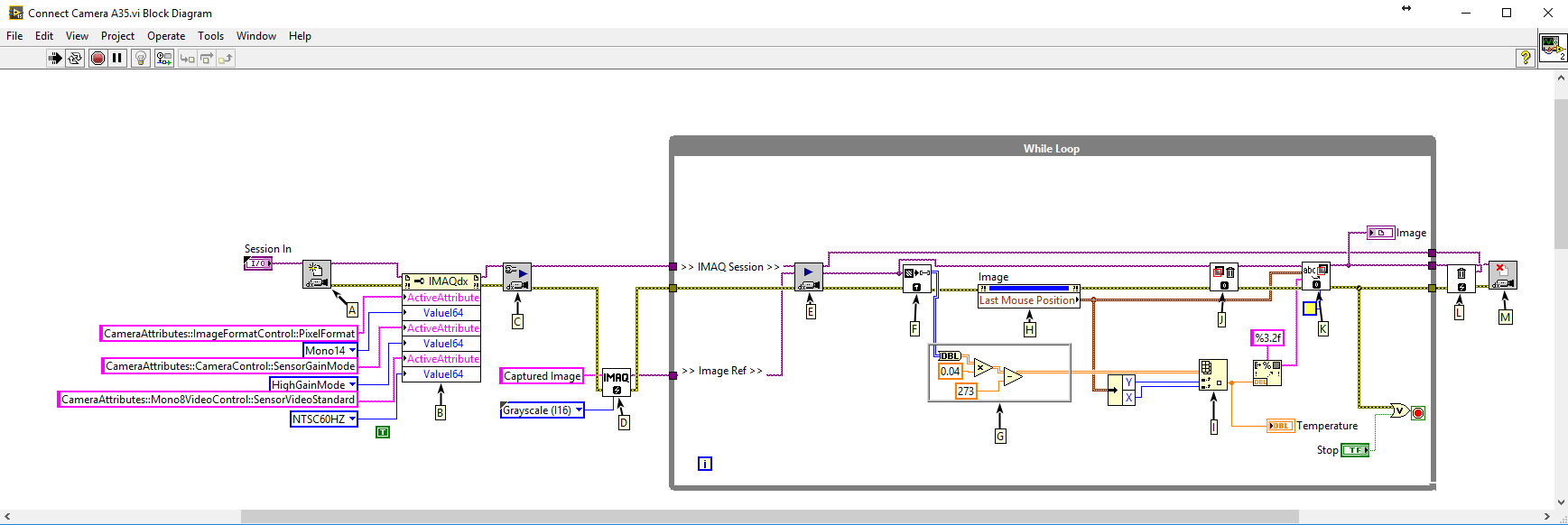
BlockDiagram FLIR A35 A65 using LabVIEW

Here is how is works:

A: Open Camera VI
This VI will query attempt to connect to the selected camera. It will load the camera configuration file and create a unique reference to the camera.

B: Property Node
This property node configures the camera settings via GeniCAM as follows:

1) Pixel Format:
Sets the pixel format to either 8-bit or 16-bit. In this example, 16 bit format is chosen.

2) Sensor Gain Mode:
This will give the temperature value in 10mK from the camera.

3) Sensor Video Standard:
This attribute will set the frame rate of the camera. Currently, it is set to 50Hz.

C: IMAQdx Configure Grab VI
Sets the camera up for grabbing images.

D: IMAQ Create VI
Is used to create a reference in memory to store the images, streaming from the camera.

E: IMAQdx Grab2 VI
Is used to acquire the most recent frame from the given memory location.

F: IMAQ ImageToArray VI
Is used to convert the image to a 2D array.

G: This function converts from 10mK to Celsius (Note: this can be replaced to calculate the temperature to Fahrenheit)

H: This property node will extract the location of the mouse cursor in the image.

I: Index Array VI
Is used to extract the temperature at a given location of the mouse pointer and display it on the front panel.

J: IMAQ Clear Overlay VI
Is used to remove the previous overlay.

K: IMAQ Overlay Text VI
Is used to write the temperature value at the location of the mouse pointer.

L: IMAQ Dispose VI
Is used to clear the memory that was allocated to store the image.

M: IMAQdx Close Camera VI
Is used to close the unique reference that was created to communicate with the camera.


2024-03-28T15:33:39-07:00Thursday, March 21, 2024|Knowledgebase|

How to grab an image from a FLIR A315 using LabVIEW

Grab an Image from a FLIR A315 Using Labview

How to grab an image and display the absolute temperature from the thermal camera FLIR A315 using LabVIEW from National Instruments.

The following instructions are intended to provide some beginner level advice and it is a “Hello World” example and a first step in how to capture a thermal image from a FLIR A315 using LabView. The FLIR A315 has a Gigabit Ethernet interface and supports the world-wide machine vision standard GeniCAM.

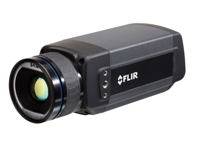
FLIR A315

Download the source code: FLIR_A315_using_LabVIEW.zip (206 KB)

Here is what you will need for this to work:

  • A PC with a LabVIEW development environment installed.
    • LabVIEW 2015 or later
    • NI Vision Development Module 2015 or later
    • IMAQdx 15.5 or later
  • FLIR A315 Thermal Camera connected to PC via Ethernet Cable
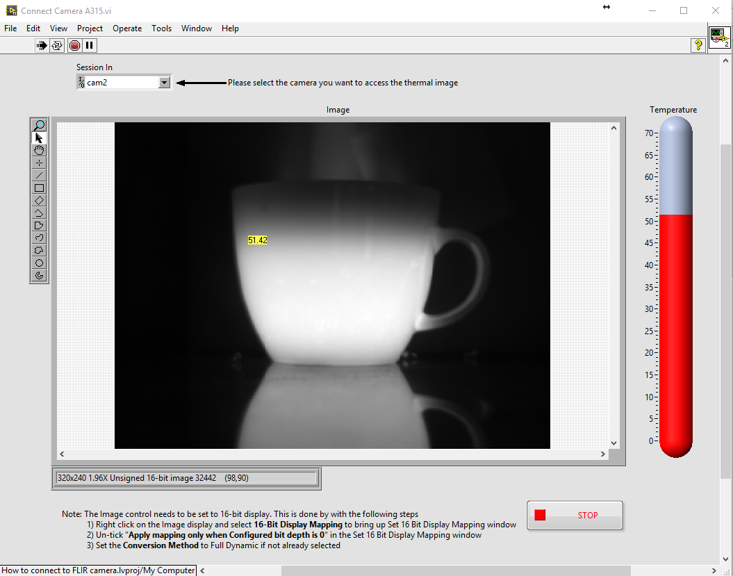
FrontPanel FLIR A315 using LabVIEW

The above is a screenshot of the LabVIEW front panel. In the center is the image display, showing a black and white thermal image of a coffee mug. The brighter the intensity, the higher the temperature. The mouse cursor was placed in the center of the cup. The temperature is superimposed onto the image. The outside of the coffee mug is 64.46 degrees Celsius in this example. Also noticeable is that the image of the mug creates a reflection on the table surface. The surface is reflective in the long wave thermal band that the camera is sensitive to (8 to 14µm).

When you run the VI, it will connect to the camera. This assumes that the camera’s IP address and subnet mask matches the PC’s settings. Instructions on how to do this would go beyond the scope of this example. Once connected, you should see a thermal image after a few seconds. When you hover your mouse pointer over the image, it will display the temperature right next to it and also update the thermometer indicator to the right of the image.

Image Grab and Temperature Measurement from FLIR A315 using LabVIEW

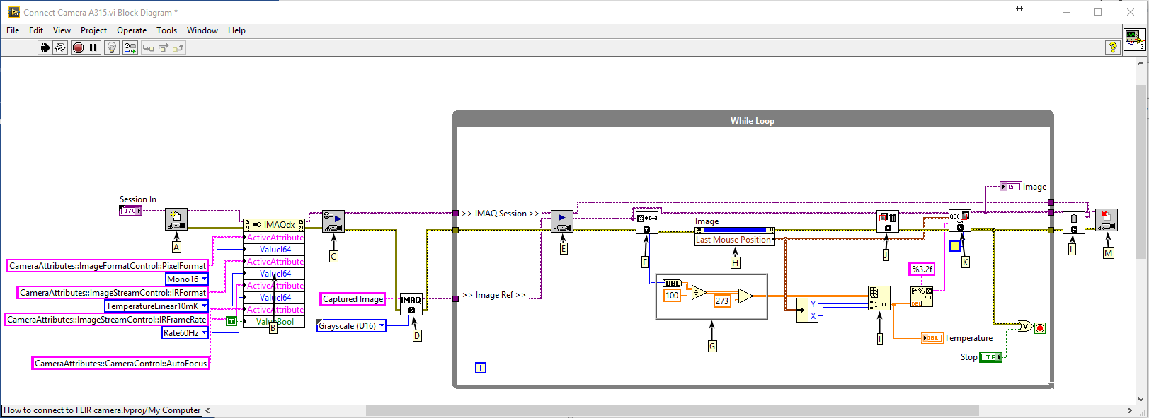
BlockDiagram FLIR A315 using LabVIEW

Here is how is works:

A: Open Camera VI
This VI will query attempt to connect to the selected camera. It will load the camera configuration file and create a unique reference to the camera

B: Property Node
This property node configures the camera settings via GeniCAM as follows:

1) Pixel Format:
Sets the pixel format to either 8-bit or 16-bit. In this example 16 bit format is chosen

2) IR Format:
This will give the temperature value in 10mK from the camera.

3) IR Frame Rate:
This attribute will set the frame rate of the camera. Currently it is set to 50Hz

4) Auto Focus:
This will send a trigger to the camera to auto focus on to an object

C: IMAQdx Configure Grab VI
Sets the camera up for grabbing images.

D: IMAQ Create VI
Is used to create a reference in memory to store the images, streaming from the camera

E: IMAQdx Grab2 VI
Is used acquire the most recent frame from the given memory location

F: IMAQ ImageToArray VI
Is used to convert the image to a 2D array

G: This function converts from 10mK to Celsius (Note: this can be replaced to calculate the temperature to Fahrenheit)

H: This property node will extract the location of the mouse cursor in the image

I: Index Array VI
Is used to extract the temperature at a given location of the mouse pointer and display it on the front panel

J: IMAQ Clear Overlay VI
Is used to remove the previous overlay

K: IMAQ Overlay Text VI
Is used to write the temperature value at the location of the mouse pointer

L: IMAQ Dispose VI
Is used to clear the memory that was allocated to store the image

M: IMAQdx Close Camera VI
Is used to close the unique reference that was created to communicate with the camera

2024-03-28T15:34:10-07:00Thursday, March 21, 2024|Knowledgebase|

How to grab an image from a FLIR A615 using LabVIEW

Grab an Image from a FLIR A615 Using LabVIEW

How to grab an image and display the absolute temperature from the thermal camera FLIR A615 using LabVIEW from National Instruments.

The following instructions are intended to provide some beginner level advice and it is a “Hello World” example and a first step in how to capture a thermal image from a FLIR A615 using LabView. The FLIR A615 has a Gigabit Ethernet interface and supports the world-wide machine vision standard GeniCAM.

FLIR A615

Download the source code: FLIR_A615_using_LabVIEW.zip (257 KB)

Here is what you will need for this to work:

  • A PC with a LabVIEW development environment installed.
    • LabVIEW 2015 or later
    • NI Vision Development Module 2015 or later
    • IMAQdx 15.5 or later
  • FLIR A615 Thermal Camera connected to PC via Ethernet Cable
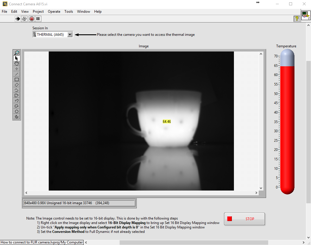
FLIR A615 LabVIEW Image Display Frontpanel

The above is a screenshot of the LabVIEW front panel. In the center is the image display, showing a black and white thermal image of a coffee mug. The brighter the intensity, the higher the temperature. The mouse cursor was placed in the center of the cup. The temperature is superimposed onto the image. The outside of the coffee mug is 64.46 degrees Celsius in this example. Also noticeable is that the image of the mug creates a reflection on the table surface. The surface is reflective in the long wave thermal band that the camera is sensitive to (8 to 14µm).

When you run the VI, it will connect to the camera. This assumes that the camera’s IP address and subnet mask matches the PC’s settings. Instructions on how to do this would go beyond the scope of this example. Once connected, you should see a thermal image after a few seconds. When you hover your mouse pointer over the image, it will display the temperature right next to it and also update the thermometer indicator to the right of the image.

Image Grab and Temperature Measurement from FLIR A615 using LabVIEW


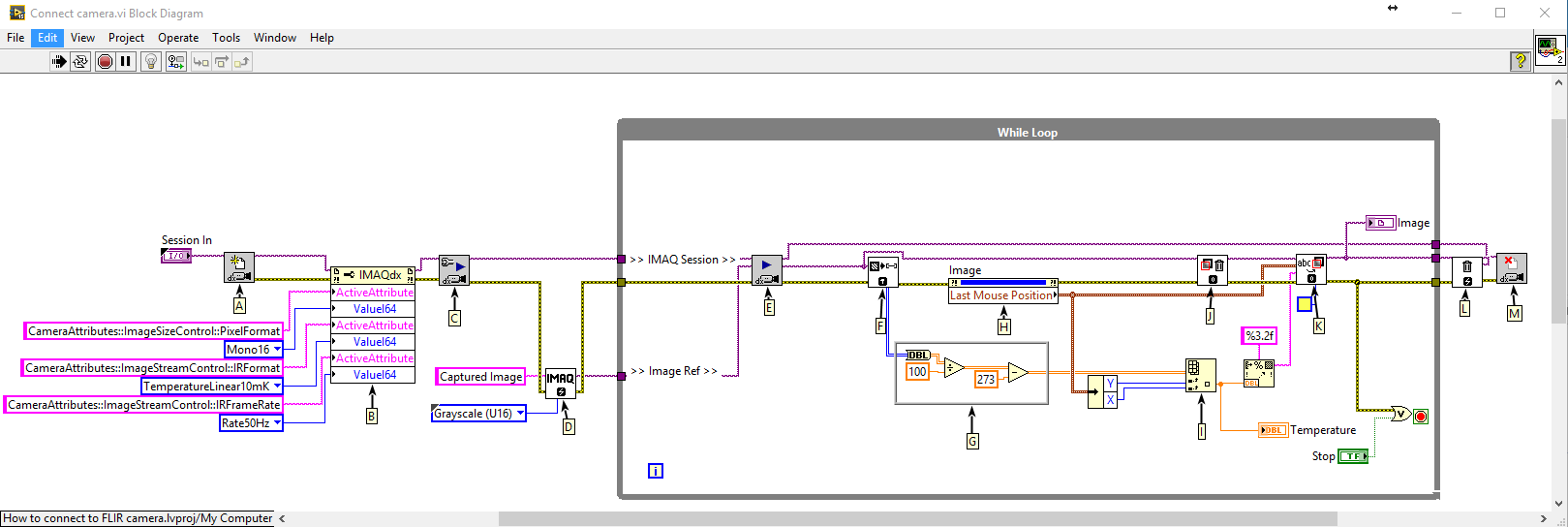
The image below is the block diagram of the code that belongs to the front panel above.

LabVIEW FLIR A615 image grab block diagram

Here is how is works:

A: Open Camera VI
This VI will query attempt to connect to the selected camera. It will load the camera configuration file and create a unique reference to the camera

B: Property Node
This property node configures the camera settings via GeniCAM as follows:

1) Pixel Format:
Sets the pixel format to either 8-bit or 16-bit. In this example 16 bit format is chosen

2) IR Format:
This will give the temperature value in 10mK from the camera.

3) IR Frame Rate:
This attribute will set the frame rate of the camera. Currently it is set to 50Hz

C: IMAQdx Configure Grab VI
Sets the camera up for grabbing images.

D: IMAQ Create VI
Is used to create a reference in memory to store the images, streaming from the camera

E: IMAQdx Grab2 VI
Is used acquire the most recent frame from the given memory location

F: IMAQ ImageToArray VI
Is used to convert the image to a 2D array

G: This function converts from 10mK to Celsius (Note: this can be replaced to calculate the temperature to Fahrenheit)

H: This property node will extract the location of the mouse cursor in the image

I: Index Array VI
Is used to extract the temperature at a given location of the mouse pointer and display it on the front panel

J: IMAQ Clear Overlay VI
Is used to remove the previous overlay

K: IMAQ Overlay Text VI
Is used to write the temperature value at the location of the mouse pointer

L: IMAQ Dispose VI
Is used to clear the memory that was allocated to store the image

M: IMAQdx Close Camera VI
Is used to close the unique reference that was created to communicate with the camera

2024-03-28T15:34:36-07:00Thursday, March 21, 2024|Knowledgebase|

Title

Go to Top