Early Fire Detection Enhances Safety
What is Early Fire Detection and Why is it Important?
Enhancing Fire Safety through Early Detection Systems
Fire incidents can have devastating consequences, causing loss of property, life, and damage to the environment. Early fire detection is crucial for preventing catastrophic outcomes, and industries are taking notice. Thermal imaging is emerging as a reliable technology for early fire detection, offering advantages over traditional smoke and heat detectors.
Several industries, including oil and gas, power plants, and manufacturing, can benefit significantly from this technology. In this article, we will compare different types of fire detection sensors, discuss their pros and cons, and explore how combining IoT technology with early fire detection systems can enhance fire safety.
What are the 4 types of fire detection?
There are four main types of fire detection devices: smoke detectors, heat detectors, flame detectors, and gas detectors. Depending on the type of device that is used, the detection timing and sensitivity may vary. Different sensors have varying levels of sensitivity when it comes to detecting fire. While some sensors can detect fires in their early stages, others can only detect them when they have spread significantly.
It is important to understand the relative detectability of each fire detection sensor at different stages of fire development. This will help facility managers choose the right sensor for their needs. The upcoming chart compares different fire detection devices at different stages of fire development. It also lists the corresponding damage levels.
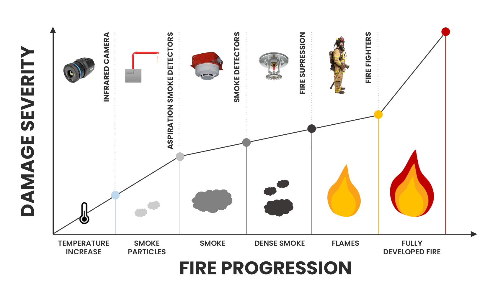
Graph of fire progression, showing infrared cameras are the first to detect fire.
Early Fire Detection and Infrared (IR) Camera Systems
IR camera systems are the first to alert before a fire develops. They see a warming-up of material early in the fire development process before forming smoke particles or flames. IR cameras operate on the heat transfer principle of radiation.
In recent years, early fire detection systems that use infrared cameras have become increasingly popular. By detecting early, infrared cameras have proved to be a valuable tool for fire prevention and safety. IR cameras give facility managers early warnings of a fire, allowing them to take action quickly and minimize damage.
Considering the Pros and Cons of Each Sensor
We have discussed the different types of devices available in the market. Now, we will discuss the pros and cons of each fire sensor and how they work.
Some sensors have higher sensitivity, allowing them to detect fires earlier. Others may be more reliable in detecting certain types of fires. By the end of this section, you will know which sensors are the most suitable for your facility.
Infrared Cameras
Infrared cameras detect fire by using the heat transfer principle of radiation. These cameras have a focal plane array of detector elements that sense infrared light radiated from object surfaces.
As a fire develops, the temperature of the surrounding materials increases. This generates a heat signature that can be detected by infrared cameras. This heat signature can be an early indication of a fire’s presence, even before smoke is visible.
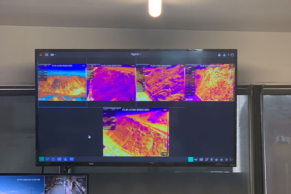
Monitor displaying thermal images of a pile being monitored by an early fire detection system.
PROs: Can detect and alert at the earliest stages of potential fire development. Are accurate and can precisely pinpoint the position of a hotpot.
CONs: Can only detect surface temperatures and require a clear line of sight to the target of interest.
Aspiration Smoke Detectors (ASD)
ASDs draw air samples to the detector using a sampling pipe with multiple holes. The air sample is filtered and processed by a sensitive laser detection unit. If smoke particles are detected, the system’s alarm is triggered. ASDs are more precise than passive smoke detectors and typically incorporate multiple alarm levels.
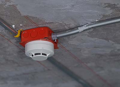
Smoke Detector
PROs: Flexible installation options due to active sampling. Detect smoke activity in large open spaces where smoke dilution can occur. Incorporates integrity monitoring and alerts when the ability to detect smoke is compromised.
CONs: Poor performance in dirty environments where fouling can occur.
Smoke Detectors
An ionization smoke detector operates by utilizing two metal plates with a small amount of radioactive material positioned between them. This material causes the air in the detector to become charged with electrically charged particles called ions. If smoke enters the detector, it disrupts the flow of ions.. This reduces the electrical current between the plates and sets off the alarm.
PROs: High responsiveness to the flaming stage of fires.
CONs: More susceptible to giving false alarms from steam or dust particle
Photoelectric Smoke Detectors
In a photoelectric smoke alarm, a light is aimed into a sensing chamber but away from the sensor itself. When smoke enters the chamber, it causes the light to be reflected onto the sensor, activating the alarm.
PROs: More responsive to slow smoldering fires that emit larger particles. They are less susceptible to false alarms.
CONs: They are slower at responding to fast-forming fires.
Fire Sprinkler Systems
Fire sprinkler systems are strategically placed sprinkler heads with glass bulbs containing a glycerin-based liquid. Sprinkler systems detect a fire through rising temperatures. Sprinkler heads activate when the temperature at the head reaches 135 to 165 degrees Fahrenheit.
This causes the liquid inside the glass bulb to expand and break the glass, activating the sprinkler head. There are various liquid colors in these glass components, each indicating a different threshold of heat required to break the glass.
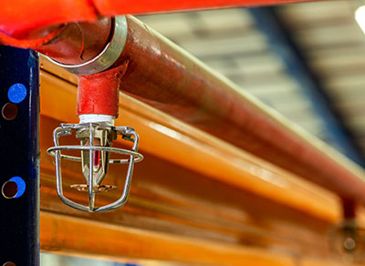
Fire Sprinkler
PROs: Detect fire and aid in extinguishing it. Only those sprinklers closest to the fire activate.
CONs: Detect late in the fire development process. Extensive installation effort.
Enhancing Fire Safety with IoT Technology
Combining IoT technology with early fire detection (EFD) systems can greatly enhance fire safety in various industries. These systems use sensors to detect fires at different stages of development and alert personnel through various communication channels. Communication options include voice calls, SMS, text, email, and push notifications. Connecting sensors that detect fires at different stages of development can help detect and prevent potential fires more effectively.
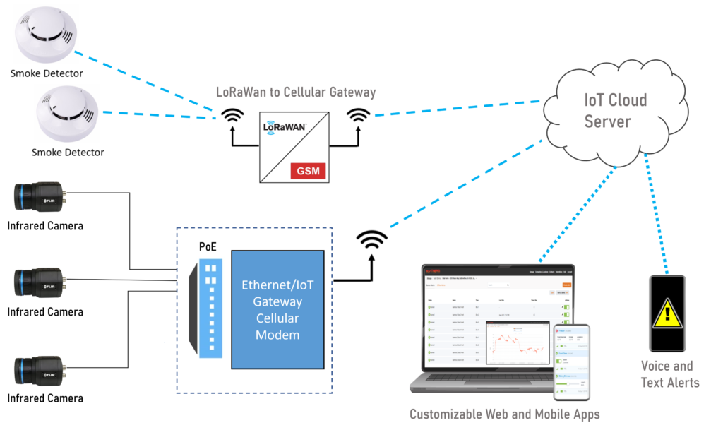
Graphic illustrating a sample of MoviTHERM’s early fire detection solution.
In addition to improving fire detection, IoT EFD systems can also improve emergency planning. By using algorithms and analytics, these systems can quickly prepare better emergency plans. Analytics can provide the number of people in the building, where the fire is located, and how quickly it is spreading. Improved emergency planning can prevent congestion by guiding workers to different building locations for optimum routing.
Contact MoviTHERM today to learn how our early fire detection solutions can help enhance your fire safety measures.


