How did the VMA’s film 30 Seconds to Mars’s live performance?
VMA’s 30 Seconds to Mars’s Live Performance
In this video, we’re going to show you the technology that was used in the 30 Seconds to Mars live performance during the MTV Video Music Awards 2017.
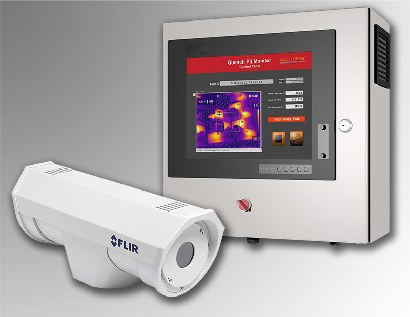
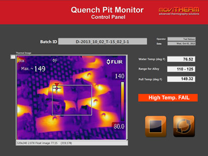
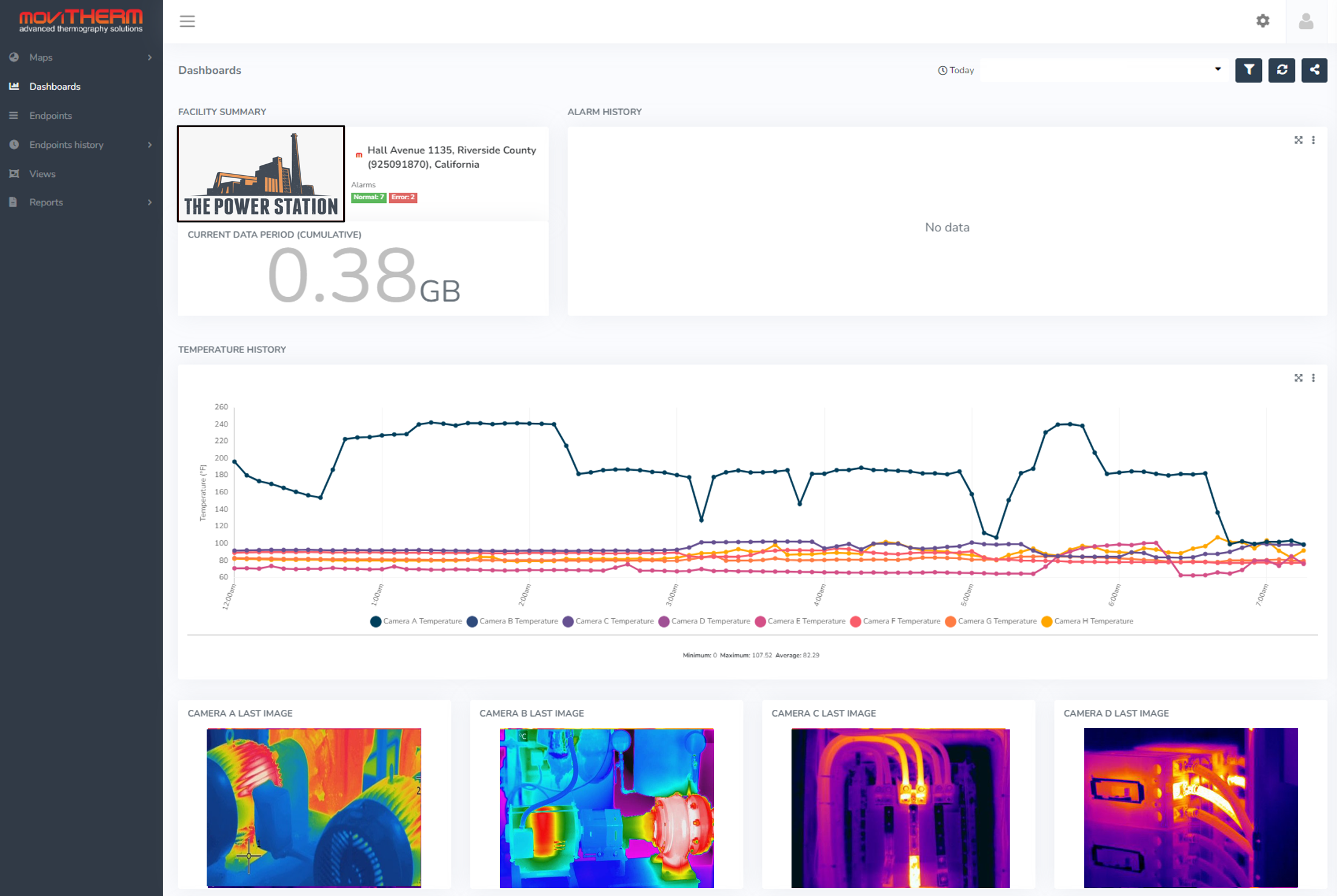
A lot of you were interested in learning more about how this effect was achieved. We were using a FLIR HD thermal camera like the FLIR A8300sc. And we had four of those on set during the live performance. We have an HD SDI video output capable of streaming 720p at 60 frames per second. This is the standard for broadcast equipment. During the show, we had this directly connected to the MTV broadcast equipment and we were controlling the camera using the Gigabit Ethernet port with our custom written software. Here’s a view of the camera image from the custom MoviTHERM software interface.
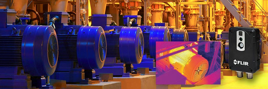
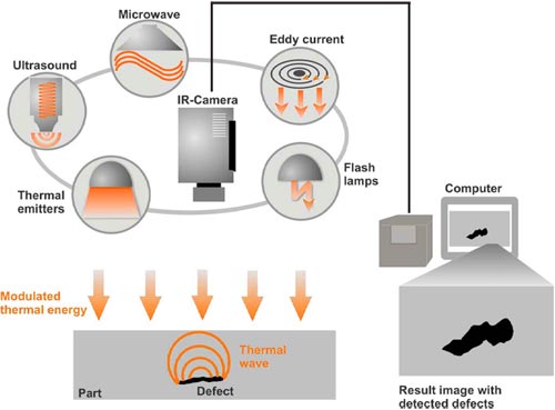
It’s important to understand that thermal cameras respond to the heat signature of the subject. The lights can be off or on it doesn’t matter. The cameras don’t respond to visible light reflecting off the subject like regular video cameras, they only respond to temperature. Human body heat or active heat sources like the propane torch will appear brighter in the image. Cooler surfaces such as the back walls appear dark unless they’re lit up by the propane torch. Notice that the propane flame is quite small in the visible image but looks very large and the thermal image is a result of the heat energy.
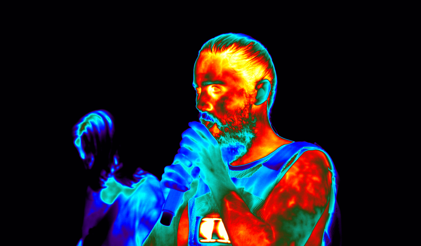
30 Seconds to Mars MTV VMA Jared Leto during the live performance
One interesting effect can be achieved by breathing into a cloth over the mouth as shown here this is one of the effects used in the live show. The custom MoviTHERM software enabled the technicians to tune the temperature sensitivity of the cameras to specific temperature ranges. These ranges were fine-tuned to optimize the colors and then adjusted in real-time to closely match the changing body temperatures of the live performers. Multiple temperature range presets and crossfade options are included in the software to further automate the camera’s response.
In collaboration with a world-class rock band, experienced creative professionals, talented choreographer and skilled video production staff the MoviTHERM team was able to dial in the dramatic colors and effects that appeared in the live MTV VMA performance.

