MoviTHERM

About MoviTHERM

This author has not yet filled in any details.
So far MoviTHERM has created 156 blog entries.

What is emissivity?

What is emissivity and why is it important?

What is emissivity?

If you want to measure absolute temperatures with a thermal camera, you must have a working understanding of “emissivity”.

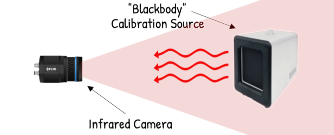
Emissivity is a measure of how well a material radiates heat. It is the ratio of the heat radiated by the material to the heat radiated by a perfect radiator (a black body) at the same temperature. It is a dimensionless number between 0 (for a perfect reflector) and 1 (for a perfect emitter).

Temperature measurements captured by a thermal camera may seem objectively easy to understand. In reality, temperature measurements are composed of three components: transmitted energy, reflected energy, and emitted or radiated energy.

emissivity, measuring absolute temperature on an object with the IR camera

Transmitted energy is the energy component that passes through the object. A common example of energy transmission is daylight streaming through a glass window.

Reflected energy is the energy bouncing off the target and back to the camera. In much the same way a polished mirror can reflect your likeness, thermal energy can also be reflected. The degree of reflection depends on the materials and surfaces.

Emitted (or radiated) energy is energy that is intrinsic to the target. This type of energy is generated by the object or the result of the temperature difference between the object and surrounding environments. Heat energy flows from the higher temperature objects to the lower temperature objects either by conduction, convection, or radiation.

Useful examples can be found in the light from a lightbulb or heat energy from an electrical heater. These energy sources give off or emit thermal heat into the surrounding environment, acting to equalize the temperature imbalance.

In most cases, when measuring the temperature of an object, we are primarily interested in the emitted, radiant energy. Transmitted and reflected energy add a bias or measurement error to the system and degrade the accuracy of measurements. Therefore, it is useful to have a practical way to express the relationship between emissivity, transmission, and reflection.

The Emissivity Formula

The Emissivity Formula provides a means to calculate the relative intensity of the energy components. The formula is expressed as:

1 = Transmission + Reflection + Emitted

This formula is based on the idea that the sum of all energy sources (transmitted, reflected, and emitted) has a combined value of 1. Each component contributes a corresponding fraction or percentage toward the total. Since we have assumed the sum of all components is 1, we can calculate the total energy that is emitted. We can do this by simply subtracting the fractional transmission and reflection components from 1.

So, by rearranging the original formula, we arrive at this:

1 – (Transmission + Reflection) = Emitted

If accurate temperature measurement is critical, then reflected and transmitted energy must be minimized. This is needed to optimize the signal to bias ratio between the emitted energy and other energy components.

Transmission Considerations

Generally, most materials don’t transmit thermal energy or thermal radiation particularly well. For this reason, lenses for thermal cameras must be constructed from unusual and often rare materials. Materials like Germanium (Ge), Sapphire or Zinc Selenide (ZnSe).

When selecting IR lens materials, care must be taken to select the correct material based on the portion of the IR spectrum that needs to be transmitted. Generally, reflective energy tends to be more of a concern than transmitted energy. It is important to note that some plastics, especially thin plastic films, are able to transmit energy in the IR spectrum. While reflection will have more impact on measurement accuracy under most circumstances, transmission may be a consideration, depending on your application.

Reflection Considerations

If you are measuring an (infrared) opaque object, the transmission will be zero, and the emissivity formula becomes:

1 – Reflection = Emitted

This simplifies the equation, but it may not reduce the complexity as much as first imagined. While transmission isn’t common, many materials reflect thermal energy. This creates two potential issues: the first concerns getting reliable measurements from a highly reflective measurement target. The second is the impact of other heat sources in the vicinity of the object of interest.

Shiny, reflective surfaces like polished metals, are the most challenging of all. In the case of polished aluminum, transmission is zero; thermal energy does not pass or transmit directly through metals. However, reflectivity is high, as much as 0.9.

If the sum of all energy is equal to 1, and reflectivity is 0.9 or 90%, then emissivity will be very low. Emissivity could be around 0.1 or 10% of the signal. On the other hand, if the same aluminum surface has a dull and dark surface, this will dramatically reduce reflection. With low reflection, and no transmission through the material, a larger percentage of the measured thermal energy will be emitted energy.

Practically speaking, polished aluminum has an emissivity of 0.1. However, if you anodize the aluminum, you can increase the emissivity of the surface up to 0.65, or better. This depends on the metal surface finish and roughness of the anodized aluminum.

Measuring object with much less than 0.65 emissivity usually does not yield very good or accurate results anymore. However, it depends on the application, part geometry, environment and particular requirements.

Emissivity Table

The previous section underscores an important point about emissivity. The emissivity of any common material depends on its composition and on its surface characteristics. Thankfully, standardized Emissivity Tables have been compiled listing many common objects and surfaces. If you need to determine the emissivity of a particular target object, the Emissivity Tables can provide a useful reference.

Emissivity Tables are available from several sources online. A quick online search using the search term “emissivity tables” will produce several links to useful resources.

Material Emissivity
Human Skin 0,98
Water 0,95
Aluminium (polished) 0,10
Aluminium (anodized) 0,65
Plastic 0,93
Ceramic 0,94
Glass 0,87
Rubber 0,90
Cloth 0,95

Other Factors Affecting Measurement Accuracy

The ambient temperature of the atmosphere (which is essentially reflected stray radiation) will also have some impact on measurements. If you want to optimize measurement accuracy, it’s worth setting the ambient temperature configuration in your thermal camera.

If the object temperature is close to the ambient air temperature, the environmental radiation will have more impact on accuracy. This is because the target has a lower emissivity value. The emissivity component based on the target’s radiation will occupy a smaller proportion of the measured values. Atmosphere and reflection, although lower in value, will comprise a larger proportion of the emissivity “pie”, as illustrated below.

emissivity pie graph

Viewing Angle can also have an impact on temperature measurements. If your camera is mounted at an angle, a percentage of the emitted energy will be lost. The amount loss will depend on the angle. The most accurate temperature measurements will be collected when the plane of the camera’s sensor is parallel to the surface.

The more the angle increases, the less emitted energy the camera’s sensor will detect. Also, the more impact environmental radiation will have on the resulting measurements.

How Hot Objects in Proximity to your Target Can Impact Measurements

As noted earlier, the impact of reflectivity will be compounded if there are hot objects in the vicinity of your target. A hot object reflecting off the surface of a shiny object can overwhelm the much smaller emissivity output.

Bright sunlight reflecting off a smooth surface will almost always impact your measurement values. As noted previously, total temperature includes reflected energy, so reflections of hot objects will add noise and degrade results. It’s always important to keep this in mind when determining the position of the camera with respect to the target.

emissivity, energy radiated from a natural heat source

Depending on the physical characteristics of the target, hot objects may also create unexpected transmission issues. If your thermal camera can see through the target material, a hot object behind it can suddenly skew your measurements.

You need to be aware of this particularly if you want to measure the surface of some plastics. Make sure you are not transmitting a significant amount of energy through your target. You may find that you are picking up the temperatures from behind your target, rather than the temperatures of your target.

emissivity, measuring absolute temperature with a thermal camera

This article touches on some of the basics of emissivity. There are other considerations as well, such as the transmission characteristics of the lens. The atmospheric effects are based on the distance between the camera and the object, and so on.

Emissivity is just one of many considerations when evaluating the temperature accuracy and suitability of thermal imaging for your applications.

For more information, contact MoviTHERM and speak with one of our IR Specialists.

2024-08-16T17:25:28-07:00Thursday, March 21, 2024|Blog|

What is thermal infrared imaging?

Thermal Infrared Imaging Explained

Thermal infrared imaging requires the use of special cameras (IR cameras). The imaging sensors in these cameras are sensitive to wavelengths in the infrared region of the electromagnetic spectrum.

Thermal infrared imaging is also referred to as “non-visible” imaging, since the infrared spectrum is not visible to the human eye. This article explains the infrared imaging spectrum and the different types of available infrared cameras and detectors used to make the invisible – visible.

Infrared Spectrum

Infrared Spectrum

Infrared Spectrum

The above illustration, from left to right, shows the visible spectrum (400nm to 700nm). That is the spectrum that we can perceive as humans with our eyes. As the wavelengths become longer, we enter the near infrared (NIR) and shortwave infrared (SWIR) region 0.9µm to 1.7µm. The segmentation in the above spectrum is based on the spectral sensitivity of the infrared camera sensors used for thermal infrared imaging.

You may find a different segmentation of the infrared spectrum in general physics literature for that reason. Adjacent to the SWIR spectral band is the midwave infrared (MWIR) band.

The extended MWIR band spans from 1µm to 5µm. The MWIR region is followed by a gap that isn’t covered from 5µm to 8µm. This gap is due to very strong atmospheric attenuation in that region.

H2O and CO2 molecules tend to attenuate the infrared radiation significantly in that region. Hence, that band is not as useful for thermal infrared imaging. Then further to the right is the longwave infrared region (LWIR). It spans from 8µm to 13µm and sometimes 14µm.

To recap, there are infrared cameras or thermal imaging cameras available with special detectors for the SWIR, MWIR and LWIR bands. Each one of these cameras have their own special thermal imaging systems that they are good for.

The majority of all thermal cameras sold and used today, operate in the LWIR band. These LWIR detectors are also called micro-bolometer detectors, or short µbolo. These detectors actually do not measure photons. Instead, they convert infrared radiation to a change in electrical resistance in their detector elements.

Cameras with Micro-Bolometer Detectors

Micro-Bolometer Pixel

Micro-Bolometer Pixel

Micro-Bolometer Pixel

The illustration above depicts a single pixel in a micro-bolometer detector of a thermal camera. The pixel size is 25µm x 25µm. The pixel has thin connection leads to reduce thermal bleed pixel element to the substrate below. Thousands of these pixels are working in conjunction to form a thermal image in a thermal camera of this type.

One drawback of this detector type is the fixed integration time. The integration time, also referred to as the exposure or shutter time in visible camera, is the time it takes a pixel to produce a useful conversion. The pixel converts infrared radiation (heat) into a change in resistance of the pixel. The connected read out electronics then converts the change in resistance into a voltage and in turn into a temperature reading for a radiometrically calibrated camera.

Some thermal cameras used for surveillance or night vision may not be able to measure absolute temperature. These type of cameras are lacking the radiometric calibration and supporting electronic.

Example cameras that contain these type of detectors are the FLIR AX8FLIR A35FLIR A65FLIR A310FLIR A315FLIR A615 and many handheld cameras. The detectors of these camera actually are made from a MEMS device and contain miniature thermocouple elements as their pixels. It takes a finite time to warm up the pixels. Typically between 8ms to 12ms, depending on detector type.

The materials used for these detectors are either Vanadium Oxide (VOX) or Amorphous Silicon (a-Si). These type of cameras are relatively inexpensive and range from $1,000 to $20,000 or above.

The pixel resolution of these cameras (or infrared thermal cameras in general) is still relatively low. Resolutions range from 80 x 60 pixels to 1.2Mp at the date of this article. A camera without calibration can only display relative hot/cold image information.

Cameras with Photon Based Detectors

Higher-end infrared cameras come with a semiconductor detector that is capable of converting photons into electrical signals. Detectors are available for all thermal bands. (SWIR, MWIR and LWIR).

These detectors are made from exotic materials and are very expensive to manufacture. Hence, cameras of this type are more expensive than their micro-bolometer counterparts. These detectors are extremely sensitive and therefore need to be cooled.

Shortwave Infrared Cameras – SWIR

These cameras have a photon converting detector made from Indium Gallium Arsenide (InGaAs). The cooling methods for these cameras range from non-cooled, thermo-electric cooled (single, double, triple stage) to cryogenically cooled for high-end scientific grade cameras. These detectors are sensitive in the 0.9µm to 1.7µm region.

Typical applications range from spectral imaging for agriculture, plastic inspection, enhanced night vision to ultra-high temperature furnace monitoring or laser weld inspection. These cameras still see a significant amount of reflected light and only start to see true thermal effects at higher surface temperatures. An example camera is the FLIR A6260sc.

Midwave Infrared Cameras – MWIR

MWIR cameras use a detector made from Indium Antimonide (InSb). These are exclusively cryogenically cooled. Modern cameras have therefore a Stirling cooler built into the camera body and do no longer require external cooling gas.

These cameras are great for taking thermal measurements rapidly fast. Since their detector is photon based, integration times of usec or msec can be achieved.

These detectors are capable of detecting temperature changes in the 0.018mK range. MWIR cameras have a very wide application range. To list a few examples: Optical Gas Imaging, Precision, high-speed temperature measurements, Military applications, Automated Thermal Imaging, Plastic Film Inspection, Microscopy etc. An example camera is the FLIR A8300sc series.

Longwave Infrared Cameras – LWIR

Camera in this category used to be equipped with a HgCdTe or Mercury Cadmium Telluride detector. These heat sensor camera detectors are extremely expensive, pushing camera prices beyond $150,000. These detectors are also very non-linear, making these cameras difficult to calibrate and work with.

A new detector technology has made its way into the market. The SLS or Super Lattice Structure detector. It is not quite as sensitive as the HgCdTe detector, but much less expensive and much more linear.

These type of cameras come into play, if the longwave infrared region is of interest to the application, but a faster integration time and more sensitivity is required. An example camera is the FLIR A6750SLS.

Example Application for Thermal Infrared Imaging

Thermal Imaging of Printed Circuit Board

Thermal Imaging of Printed Circuit Board

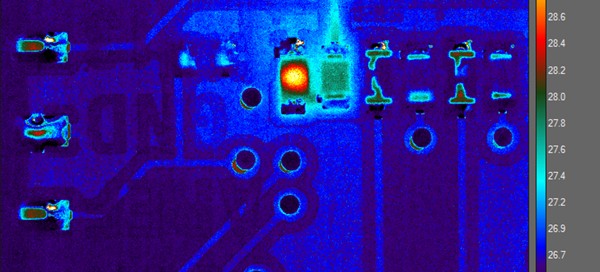
The image above is a thermal image taken with a microbolometer camera type. The bar on the right hand side indicates the temperature range of the thermal image. The orange color indicates a hot component – in this case a resistor. The rest of the circuit board is blue in color, associated with a much colder temperature.

Printed circuit board inspection is a very common use for thermal imaging. It allows the visualization of temperature. In other words, it allows for a non-contact method of temperature measurement.

Using a thermal camera for printed circuit board inspection can aid with troubleshooting as well as thermal design for thermal management in board design. In addition to a thermal camera, the user will also need a capable thermal imaging software to support the effort.

Thermal Infrared Imaging Cameras do not rely on external illumination. They can “see” heat and can be very useful wherever non-contact temperature measurements are of interest.

If you need help with selecting the right camera for your next application, please do not hesitate to contact us with any of your question regarding thermal or infrared imaging!

2024-08-16T17:25:39-07:00Thursday, March 21, 2024|Blog|

How did the VMA’s film 30 Seconds to Mars’s live performance?

VMA’s 30 Seconds to Mars’s Live Performance

In this video, we’re going to show you the technology that was used in the 30 Seconds to Mars live performance during the MTV Video Music Awards 2017.

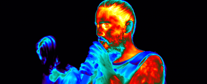
A lot of you were interested in learning more about how this effect was achieved. We were using a FLIR HD thermal camera like the FLIR A8300sc. And we had four of those on set during the live performance. We have an HD SDI video output capable of streaming 720p at 60 frames per second. This is the standard for broadcast equipment. During the show, we had this directly connected to the MTV broadcast equipment and we were controlling the camera using the Gigabit Ethernet port with our custom written software. Here’s a view of the camera image from the custom MoviTHERM software interface.

It’s important to understand that thermal cameras respond to the heat signature of the subject. The lights can be off or on it doesn’t matter. The cameras don’t respond to visible light reflecting off the subject like regular video cameras, they only respond to temperature. Human body heat or active heat sources like the propane torch will appear brighter in the image. Cooler surfaces such as the back walls appear dark unless they’re lit up by the propane torch. Notice that the propane flame is quite small in the visible image but looks very large and the thermal image is a result of the heat energy.

30 Seconds to Mars MTV VMA Jared Leto

30 Seconds to Mars MTV VMA Jared Leto during the live performance


One interesting effect can be achieved by breathing into a cloth over the mouth as shown here this is one of the effects used in the live show. The custom MoviTHERM software enabled the technicians to tune the temperature sensitivity of the cameras to specific temperature ranges. These ranges were fine-tuned to optimize the colors and then adjusted in real-time to closely match the changing body temperatures of the live performers. Multiple temperature range presets and crossfade options are included in the software to further automate the camera’s response.

In collaboration with a world-class rock band, experienced creative professionals, talented choreographer and skilled video production staff the MoviTHERM team was able to dial in the dramatic colors and effects that appeared in the live MTV VMA performance.

2024-08-16T17:25:49-07:00Thursday, March 21, 2024|Blog|

Quench Pit Monitoring with Thermal Imaging

Quench Pit Monitoring Application Using Thermal Imaging

Overview Quench Pit Monitoring System

Heat treating is used in metal manufacturing to alter the chemical and physical properties of the resulting metal parts. Careful application of a specific sequence of heating and cooling cycles for pre-determined time intervals enables metallurgists to control the hardness or softness of the resulting parts.

Maintaining tight control over heating and quenching sequences is very important to companies that manufacture wear parts for industrial applications. By controlling heating and cooling cycles, manufacturers can regulate the relative hardness of machine components, making easily replaced “wear components” softer, while critical mechanical parts can be harder. Wear parts help to prolong the life of machines, and reduce service and maintenance costs in the field.

quench pit monitoring

Figure 1: Parts above the Quench Pit following a cooling cycle

FLIR integration partner MoviTHERM (Irvine, CA) was approached by a prominent manufacturer of wear parts to design and deploy a thermal imaging system to inspect parts immediately following a critical quenching process.

Process Sequence

The parts to be inspected are first heated in a kiln to temperatures approaching 2,000 °F. After heating, the parts are transferred to a liquid cooling chamber or “Quench Pit”, for quenching. After some time has elapsed, the parts are removed from the cooling chamber, and the temperatures of the parts are measured.

A FLIR A310f thermal camera captures an image. Hot spots in the image are examined to see if additional cooling cycles will be necessary to bring all parts below a pre-defined temperature limit. The critical process components are depicted in Figure 2.

quench pit monitoring process

Figure 2: Key System Components

quench pit monitoring parts in thermal

Figure 3: Thermal Image of Hot Parts

Key Components of the Inspection System

The inspection system hardware is depicted in Figures 4 and 5.

quench pit monitoring solution

Figure 4: Photo of System Components

quench pit monitoring solution

Figure 5: Control System Hardware Overview

FLIR A310f Thermal Camera Specifications

That Camera used in this Quench Pit Monitoring System has:

  • Environmental housing with specifications to IP66
  • 45° Lens
  • High sensitivity to < 50 mK
  • 16 bit image resolution
  • 100Mb Ethernet
  • PoE (Power over Ethernet)

Software User Interface

The system is controlled via a touchscreen mounted on the front face of the electrical panel. The operator configures the inspection at the start of the sequence, and the Inspection System tracks the motion of the parts into and out of the cooling chamber.

quench pit monitoring

Figure 6 shows the HMI screen layout for the Inspection Results Screen.

The most prominent item in this screen image is the purple and orange Thermal Image on the left side of the panel. The FLIR A310f camera passes an image to the Analysis PC image at the completion of the quench cycle. The brighter regions in the image reflect higher temperatures, with the whitest areas being the hottest. Black areas are the coolest, with purple and eventually orange areas representing increasing temperatures from 80°F to 140°F , as reflected in the and vertical legend in the left side of the thermal image. In this instance, the parts are still above the target temperature range, so the operator can repeat the quench cycle by selecting the Looping Arrow button in the lower right-hand corner of the touch-enabled screen.

2024-08-16T17:25:59-07:00Thursday, March 21, 2024|Blog|

Machine Condition Monitoring for Rotating Machinery

Machine Condition Monitoring Using Infrared Cameras

At the pace of modern business today, no one can afford unplanned downtime and costly outages. Cloud-based machine condition monitoring is helping facilities avert problems before they happen. By connecting various sensing technologies with the internet of things (IoT) and moving condition monitoring software to the cloud, maintenance professionals can easily and readily monitor machinery and rotating equipment in real time from any location.

In this article, we discuss how cloud-based condition monitoring using infrared thermography improves the situational awareness of asset health. Thus, making predictive maintenance more efficient and effective, saving companies time and money.

machine condition monitoring with thermal camera

Machine Condition Monitoring Using Thermal Imaging

Preventative, Predictive, & Reactive Maintenance

The sweet spot for a maintenance program falls between the “degradation start” point and the “potential failure” point of a machine’s life (see chart below). Work performed on a mechanical piece of equipment during the “normal state” period might be effective for asset health and facility uptime, producing the desired outcome. However, it is less efficient because maintenance resources are deployed on equipment that may not necessarily require upkeep or repair. Any work or investment in healthy machines in the “normal state” produces a certain amount of waste.

Alternatively, maintenance efforts and costs become reactive if the machine asset condition is allowed to degrade beyond the “potential failure” point. In this stage, maintenance professionals find themselves chasing problems with machine performance severely compromised and facility downtime highly probable. Maintenance costs in this phase can accelerate rapidly with additional company losses due to lost output and production.

Maintenance Modes, Asset Condition vs Time to Failure

Maintenance Modes, Asset Condition vs Time to Failure

Identifying equipment degradation at the earliest stage beyond the “normal state” is optimal for predictive maintenance. Maintenance professionals can be alerted at the earliest signs of machine failure by monitoring asset conditions with real-time data from oil analysis, ultrasound, vibration, and thermal imaging sensing.

By predicting when machine failure may occur, condition based maintenance can be carried out with machine repairs made according to the priority of equipment needs. Maintenance and repair costs can be optimized by eliminating rush orders for parts and conducting services during planned outages and turnarounds.

Thermal Imaging

Thermal imaging is one of the four modalities used in condition based monitoring. Thermal imaging is a proven and effective way to monitor equipment health and detect potential failure points before a failure can occur. Critical in-service health and wear characteristics of electrical and mechanical equipment can be assessed using thermal imaging. Longitudinal temperature data is valuable to predictive maintenance programs.

Thermal imaging is perhaps the easiest non-contact temperature measurement method available. Monitoring mechanical components such as motors, bearings, heat exchangers, cooling fans, exhaust vents, pipes, and more for “hot spots” can alert of possible future fail points. In addition, thermal scans of electrical components, such as cables, wiring, terminals, and control panels, can quickly reveal problems. Examples of problems include load imbalance, current overload, loose wires, corroded terminals, or heat management issues.

Thermal imaging makes these otherwise invisible problems visible so corrective action can be taken before catastrophic failure. Deploying IR cameras to monitor critical equipment can be a very effective first line of defense against unexpected and unplanned downtime.

Thermal Image of Electric Motors

Thermal Image of Electric Motors

Thermal Image of Motors and Pumps

Thermal Image of Motors and Pumps

How do Infrared Cameras Work?

Infrared (IR) cameras operate on the heat transfer principle of radiation. The IR camera has a focal plane array of detector elements that sense infrared light from object surfaces. The radiation captured by the IR camera detector is digitized, converted to data, and displayed as a viewable image.

Calibrated IR cameras can report temperature measurements from specific spots, lines, and areas on live or recorded images. IR cameras are available in different wavebands, pixel resolutions, lens configurations, and communication protocols to meet various installation requirements.

IR cameras are available in fixed-mount and portable handheld configurations. Handheld IR cameras are battery powered with onboard recording capabilities. Inspectors will use handheld IR cameras to conduct routine mechanical and electrical equipment checks. The inspection results are uploaded to reporting software and compared over time. The inspector then looks for any changes in the thermal profile that could indicate a compromise in asset condition.

Fixed-mount IR cameras allow for real-time monitoring and are typically used for tracking critical assets. Camera imagery and data output are uploaded to a facility computer server or cloud-based condition monitoring software. Results are viewed in real-time with alarms and notifications available to inform key maintenance personnel when problems arise.

What is IoT (Internet of Things)?

The internet of things (IoT) refers to interconnected sensors, instruments, and other devices networked into software applications that use predictive analytics and artificial intelligence (AI). These connected networks create systems that monitor, collect, exchange, analyze, and deliver valuable insights into a system or process. IoT revolutionizes condition monitoring by using cloud computing to simplify integration, enhance system control, expand situational awareness, and improve end-user decision making.

IoT and Condition Monitoring

Condition monitoring of machines and rotating equipment is an area that realizes the benefits of thermal imaging when combined with IoT and a condition monitoring software. By connecting infrared cameras and other sensors, machine health can more readily be monitored and failures prevented. Using cloud-based software makes for easy set-up, configuring, and remote monitoring.

MoviTHERM iCM for Machine Condition Monitoring

MoviTHERM iCM is a cloud-based intelligent machine condition monitoring solution. The solution uses thermal imaging and other condition monitoring sensors to provide a holistic understanding of machine asset health. By leveraging IoT connectivity with cloud computing, iCM more efficiently monitors and alerts for potential machine and rotating equipment failure. Because the iCM condition monitoring software resides in the cloud, it has low installation and reduces maintenance costs.

Customized Reports and Notifications

MoviTHERM iCM incorporates a customized asset health reporting tool to keep key personnel automatically and routinely informed. Automated reports can include imagery, measurement trends, alarm status, and more. Report frequency and recipients are easily configured for delivery to the personnel responsible for machine maintenance.

The iCM condition notifications are programable and sent when measurement thresholds are breached, or the monitoring system’s health is compromised. Communication options for notifications include voice calls, texts, and emails to establish quick and effective awareness. Notifications can be sent to select groups or individuals with links to dashboards, maps, and custom views.

Dashboards and Views

MoviTHERM iCM dashboards are an effective tool for quick condition evaluation of all monitored assets. Dashboards are customizable to display imagery and sensor measurements for any connected imager and sensor. Sensor alarm and system health status are readily visible with sensor measurement trend charts. All dashboard data is exportable and easily integrated into popular CMMS (computerized maintenance management system) software platforms.

MoviTHERM iCM views are custom displays that show facility schematics, maps, or overhead photos with sensor location, output, and real time condition. A green check or red cross quickly identifies an alarm condition for the shown sensor. Recorded visible or infrared images can be scrolled through to access historical conditions.

All dashboards and views are accessed with any internet connected smart device or computer. Additionally, all dashboards and views are readily shared by forwarding the associated web link. The access and sharing of dashboards and views is a significant advantage of the iCM cloud-based condition monitoring system.

MoviTHERM iCM Dashboard

MoviTHERM iCM Dashboard

MoviTHERM iCM Site Location View

MoviTHERM iCM Site Location View

Expandability and Scalability

Another critical advantage of MoviTHERM iCM is how easily it can be expanded and scaled. Once the cloud-based infrastructure is in place, additional sensors are added to the condition monitoring system with just a few clicks of the software application. Remote access via an internet connected device allows sensors to be added in the field at the sensor location.

MoviTHERM iCM can quickly scale to connect and monitor multiple plants and locations. This functionality allows facility managers to monitor multiple locations from a central monitoring and alarming dashboard. Understanding the situation at all facilities allows for the efficient overall management of various systems from a single control point.

Example iCM Dashboard View for Monitoring Multiple Facilities

Example iCM Dashboard View for Monitoring Multiple Facilities

Lower Maintenance and Cost

Cloud-based condition monitoring systems are less expensive to install and maintain compared to traditional monitoring systems. Because the condition monitoring software application resides in the cloud, there is no need for a dedicated facility computer server.

Any potential for operating system software conflicts is eliminated as access to the software application only requires an internet connection. Users access the condition monitoring system anywhere and anytime with any internet connected device. And with the appropriate credentials, control and alarm settings can be modified remotely to optimize performance.

Example iCM Configuration

Example iCM Configuration for Machine Monitoring

Conclusion

The power of IoT combined with cloud technology makes for efficient data gathering and transmission, which leads to faster predictive maintenance strategies.

Infrared cameras are a good way to monitor machine conditions because they provide both temperature and thermal imaging information on the same screen. The data gathered from thermal imaging can be quickly evaluated and manually archived for later analysis by a technician.

MoviTHERM iCM is a powerful and affordable condition monitoring solution. Regardless of your equipment type or level of complexity, keeping an eye on all the threats to machine health is vital to extending the life of your equipment and monitoring degradation in real time. With access to thermal imaging, you’ve got one more layer of protection in your pocket for staying on top of any potential issues.

Buyer’s Guide for Condition Monitoring

Find All Your Answers in Our Guide

condition monitoring buyer's guide download
  • What types of sensors can I connect to the system?

  • How does the system keep my data safe from hackers?

  • Does the system alert of potential failures?

  • Does the system automatically save historical data?

  • Which type of system will save you money in the long run?

2024-08-16T17:26:09-07:00Thursday, March 21, 2024|Blog|

Early Fire Detection Enhances Safety

What is Early Fire Detection and Why is it Important?

Enhancing Fire Safety through Early Detection Systems

Fire incidents can have devastating consequences, causing loss of property, life, and damage to the environment. Early fire detection is crucial for preventing catastrophic outcomes, and industries are taking notice. Thermal imaging is emerging as a reliable technology for early fire detection, offering advantages over traditional smoke and heat detectors.

Several industries, including oil and gas, power plants, and manufacturing, can benefit significantly from this technology. In this article, we will compare different types of fire detection sensors, discuss their pros and cons, and explore how combining IoT technology with early fire detection systems can enhance fire safety.

What are the 4 types of fire detection?

There are four main types of fire detection devices: smoke detectors, heat detectors, flame detectors, and gas detectors. Depending on the type of device that is used, the detection timing and sensitivity may vary. Different sensors have varying levels of sensitivity when it comes to detecting fire. While some sensors can detect fires in their early stages, others can only detect them when they have spread significantly.

It is important to understand the relative detectability of each fire detection sensor at different stages of fire development. This will help facility managers choose the right sensor for their needs. The upcoming chart compares different fire detection devices at different stages of fire development. It also lists the corresponding damage levels.

Graph of fire progression, showing infrared cameras are the first to detect fire.

Graph of fire progression, showing infrared cameras are the first to detect fire.

Early Fire Detection and Infrared (IR) Camera Systems

IR camera systems are the first to alert before a fire develops. They see a warming-up of material early in the fire development process before forming smoke particles or flames. IR cameras operate on the heat transfer principle of radiation.

In recent years, early fire detection systems that use infrared cameras have become increasingly popular. By detecting early, infrared cameras have proved to be a valuable tool for fire prevention and safety. IR cameras give facility managers early warnings of a fire, allowing them to take action quickly and minimize damage.

Considering the Pros and Cons of Each Sensor

We have discussed the different types of devices available in the market. Now, we will discuss the pros and cons of each fire sensor and how they work.

Some sensors have higher sensitivity, allowing them to detect fires earlier. Others may be more reliable in detecting certain types of fires. By the end of this section, you will know which sensors are the most suitable for your facility.

Infrared Cameras

Infrared cameras detect fire by using the heat transfer principle of radiation. These cameras have a focal plane array of detector elements that sense infrared light radiated from object surfaces.

As a fire develops, the temperature of the surrounding materials increases. This generates a heat signature that can be detected by infrared cameras. This heat signature can be an early indication of a fire’s presence, even before smoke is visible.

Fire detection system being displayed on a big monitor in control room. In the monitor display you see thermal images of thermal monitoring.

Monitor displaying thermal images of a pile being monitored by an early fire detection system.

PROs: Can detect and alert at the earliest stages of potential fire development. Are accurate and can precisely pinpoint the position of a hotpot.

CONs: Can only detect surface temperatures and require a clear line of sight to the target of interest.

Aspiration Smoke Detectors (ASD)

ASDs draw air samples to the detector using a sampling pipe with multiple holes. The air sample is filtered and processed by a sensitive laser detection unit. If smoke particles are detected, the system’s alarm is triggered. ASDs are more precise than passive smoke detectors and typically incorporate multiple alarm levels.

smoke detector

Smoke Detector

PROs: Flexible installation options due to active sampling. Detect smoke activity in large open spaces where smoke dilution can occur. Incorporates integrity monitoring and alerts when the ability to detect smoke is compromised.

CONs: Poor performance in dirty environments where fouling can occur.

Smoke Detectors

An ionization smoke detector operates by utilizing two metal plates with a small amount of radioactive material positioned between them. This material causes the air in the detector to become charged with electrically charged particles called ions. If smoke enters the detector, it disrupts the flow of ions.. This reduces the electrical current between the plates and sets off the alarm.

PROs: High responsiveness to the flaming stage of fires.

CONs: More susceptible to giving false alarms from steam or dust particle

Photoelectric Smoke Detectors

In a photoelectric smoke alarm, a light is aimed into a sensing chamber but away from the sensor itself. When smoke enters the chamber, it causes the light to be reflected onto the sensor, activating the alarm.

PROs: More responsive to slow smoldering fires that emit larger particles. They are less susceptible to false alarms.

CONs: They are slower at responding to fast-forming fires.

Fire Sprinkler Systems

Fire sprinkler systems are strategically placed sprinkler heads with glass bulbs containing a glycerin-based liquid. Sprinkler systems detect a fire through rising temperatures. Sprinkler heads activate when the temperature at the head reaches 135 to 165 degrees Fahrenheit.

This causes the liquid inside the glass bulb to expand and break the glass, activating the sprinkler head. There are various liquid colors in these glass components, each indicating a different threshold of heat required to break the glass.

fire sprinkler

Fire Sprinkler

PROs: Detect fire and aid in extinguishing it. Only those sprinklers closest to the fire activate.

CONs: Detect late in the fire development process. Extensive installation effort.

Enhancing Fire Safety with IoT Technology

Combining IoT technology with early fire detection (EFD) systems can greatly enhance fire safety in various industries. These systems use sensors to detect fires at different stages of development and alert personnel through various communication channels. Communication options include voice calls, SMS, text, email, and push notifications. Connecting sensors that detect fires at different stages of development can help detect and prevent potential fires more effectively.

iEFD for Industrial Laundry example of system

Graphic illustrating a sample of MoviTHERM’s early fire detection solution.

In addition to improving fire detection, IoT EFD systems can also improve emergency planning. By using algorithms and analytics, these systems can quickly prepare better emergency plans. Analytics can provide the number of people in the building, where the fire is located, and how quickly it is spreading. Improved emergency planning can prevent congestion by guiding workers to different building locations for optimum routing.

Contact MoviTHERM today to learn how our early fire detection solutions can help enhance your fire safety measures.

20+ Page Guide to Fire Detection Systems

Find All Your Answers in Our Guide

Infrared Non-destructive Testing Guide
  • Find a reliable fire detection system.
  • Save money in the long run.

  • Know the must-have features.
  • Find a system that adapts to your business needs.

  • Understand the importance of safety and security.
2024-08-16T17:29:06-07:00Thursday, March 21, 2024|Blog|

How to set up the IP address on the MoviTHERM MIO

Set up the IP Address on the MoviTHERM MIO

This video shows you how to set the device IP address on your MoviTHERM MIO.

The MoviTHERM MIO Series – Intelligent I/O Module for FLIR® Cameras – supporting one of the following Camera models: FLIR AX8, FLIR FC Series R or FLIR A310

Remote Monitoring Applications Made Simple

More info about the MoviTHERM MIO Series Intelligent I/O Modules

Before we get started, there is one thing to keep in mind: If you change the MIO’s IP address, just remember that any cameras connected to your MIO network must be on the same subnet as the MIO. So, that means if you change the MIO subnet, you may also need to update the camera IP addresses accordingly.

Ok, let’s get started. First, we need to open a browser window and log into your MIO. So, let’s launch the Google Chrome browser, key in the default MIO IP address, which is 192.168.1.2, and then log in to the MIO. The default MIO password is “password” so let’s type that in and open the Device Settings page.

The Device IP Address field is located toward the bottom of the settings page, under the Network Configuration heading. Just key in the new IP address (and Subnet mask if necessary), then click, “Save Settings and Reboot”.

After the MIO reboots, we can log-in again to verify the change. And there it is!

That’s all you need to do to set the IP address on your MoviTHERM MIO!

Thanks for watching, and remember to view the other how-to videos in this series for additional tips on setting up your MIO system!

2024-08-30T15:58:30-07:00Thursday, March 21, 2024|Support|

How to set up a digital output on the MoviTHERM MIO

Set up a Digital Output on the MoviTHERM MIO

This video shows you how to set up a digital output channel on the MoviTHERM MIO.

The MoviTHERM MIO Series – Intelligent I/O Module for FLIR® Cameras – supporting one of the following Camera models: FLIR AX8, FLIR FC Series R or FLIR A310

Remote Monitoring Applications Made Simple

More info about the MoviTHERM MIO Series Intelligent I/O Modules

We start with the assumption that you have already set up an inspection region in your camera. If you haven’t configured your camera yet, other videos in this series can help get you started. Please view them and set up your camera first before watching this video.

Ok, now that you have an inspection region set up in your camera, the first step is to open a browser window and log into your MIO. We will launch the Google Chrome browser, key in the default MIO IP address, which is 192.168.1.2, and log in to the MIO. The default MIO password is “password” so let’s type that in and get started.

Once we have logged in, we want to select the “Script Commands” tab. Click on the tab, and select a command for digital channel 0. We want to set an alarm based on the maximum temperature of an inspection region, so we will select the “Box Max Temperature” option, and then map ROI 1 to the Channel zero output. Next, we need to set the temperature limit for the alarm. We set a temperature limit of 30 degrees Celsius, and save the configuration to store and activate the alarm.

If we jump over to the Debug Page, we can see that our alarm is now responding and setting the Channel 0 output as expected.

That’s all you need to do to configure a digital output channel on the MoviTHERM MIO.

View the other how-to videos in this series for additional tips on setting up your MIO system!

2024-08-30T15:58:16-07:00Thursday, March 21, 2024|Support|

How to set the device name on the MoviTHERM MIO

Set Device Name on the MoviTHERM MIO

This video shows you how to set the device name on your MoviTHERM MIO.

The MoviTHERM MIO Series – Intelligent I/O Module for FLIR® Cameras – supporting one of the following Camera models: FLIR AX8, FLIR FC Series R or FLIR A310

Remote Monitoring Applications Made Simple

More info about the MoviTHERM MIO Series Intelligent I/O Modules

The first step is to open a browser window and log into your MIO. We will launch the Google Chrome browser, key in the default MIO IP address, which is 192.168.1.2, and then log in to the MIO. The default MIO password is “password” so let’s type that in and get started.

The Device Name field can be found on the Device Settings tab, which is the tab you will see after logging in.

You can find the editing field under the Device Information heading. Just key the new name of your choice into the text field, then click, “Save Settings and Reboot”.

The Device Name can be very useful if you are accessing multiple MIO units from a single PC.

After the MIO reboots, we can log-in again to verify the change. And there it is!

That’s all you need to do to set the device name on your MoviTHERM MIO!

View the other how-to videos in this series for additional tips on setting up your MIO system!

2024-08-30T15:58:04-07:00Thursday, March 21, 2024|Support|

How to set up a 4-20mA output on the MoviTHERM MIO

Set Up a 4-20mA Output on the MoviTHERM MIO

This video shows you how to set up a 4 to 20mA analog output channel on the MoviTHERM MIO.

The MoviTHERM MIO Series – Intelligent I/O Module for FLIR® Cameras – supporting one of the following Camera models: FLIR AX8, FLIR FC Series R or FLIR A310

Remote Monitoring Applications Made Simple

More info about the MoviTHERM MIO Series Intelligent I/O Modules

We start with the assumption that you have already set up an inspection region in your camera. If you haven’t configured your camera yet, other videos in this series can help get you started. Please view them and set up your camera first before continuing with this video.

Ok, now that you have an inspection region set up in your camera, the first step is to open a browser window and log into your MIO. We will launch the Google Chrome browser, key in the default MIO IP address, which is 192.168.1.2, and log in to the MIO. The default MIO password is “password” so let’s type that in and get started.

Once we have logged in, we want to select the “Script Commands” tab. Click on the tab, and select a command for analog channel 0. We want to map the maximum temperature of an inspection region to the channel 0, 4 to 20mA output. We start by selecting the “Box Max Temperature” option, and then select ROI 1 for the Channel 0 output. Next, we need to set the temperature range mapping. We set the temperature scale limits to the range limits of our camera — in this case, -20 to 120 degrees Celsius, based on the low temperature range of our A310 camera. Next, we save the configuration to activate the 4 to 20mA output.

If we jump over to the Debug Page, we can see that our 4 to 20 mA output is now responding and is updating the Channel 0 output as expected across the 4 to 20mA range.

That’s all you need to do to configure an analog output channel on the MoviTHERM MIO.

View the other how-to videos in this series for additional tips on setting up your MIO system!

2024-08-30T15:57:50-07:00Thursday, March 21, 2024|Support|
Go to Top