Connecting Your FLIR (A50/A70/A400/A700) Camera to Your Network
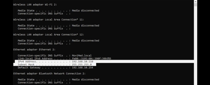
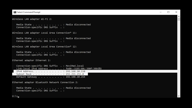
How to Connect Your FLIR Camera to Your Network Step-by-Step Guide: Connecting Your FLIR (A50/A70/A400/A700) Camera to Your Network In this article, we will walk you through the steps on how to connect your FLIR camera to your network. We will cover how to find your computer's subnet, how to locate your camera's [...]


