MoviTHERM

About MoviTHERM

This author has not yet filled in any details.
So far MoviTHERM has created 156 blog entries.

How to set up an inspection region on a FLIR A310 camera

Set up an Inspection Region on a FLIR A310 Camera

This video shows you how to set up an Inspection Region on your FLIR A310 camera.

The MoviTHERM MIO Series – Intelligent I/O Module for FLIR® Cameras – supporting one of the following Camera models: FLIR AX8, FLIR FC Series R or FLIR A310

Remote Monitoring Applications Made Simple

More info about the MoviTHERM MIO Series Intelligent I/O Modules

Before you can use the MIO to detect and respond to temperatures, you first need to set up an inspection area or “region of interest” in the image. This video shows you how to set up that “region or interest” (or ROI) using the FLIR IR Monitor software. But before we can move on with this video, be sure to confirm that:

1) you have FLIR IR Monitor software installed on your PC, and

2) your A310 camera is able to communicate with your PC over an Ethernet connection

If you are not familar with the FLIR IR Monitor software, you can find the installation files on a disk that ships with the A310 camera. If you are unsure about how to assign an IP address to your A310, please refer to the video in this series devoted specifically to setting the A310’s IP address.

Ok, if you have IR Monitor software installed and are communicating with your camera over Ethernet, you are ready to go. The first step is to launch the FLIR IR Monitor application. If this is the first time running the software, you will need to start by selecting the camera. Click in the IR Monitor window to open the Camera Selection Dialog. All connected cameras will appear in the “Available Cameras” pane on the left. (If you have multiple cameras connected, you should see all of the cameras in the “Available Camera” list.)

Select the camera you would like to configure, then click and drag it to the “Camera Grid” region on the right. Next, click “View Cameras in grid” to exit the dialog and switch to the live camera view.

In the Live View mode, you should see a thermal image on the left, and various controls on the right. Let’s go ahead and change to color palette mapping to the Ironbow palette to enhance the visualization. Pull down the Palette control and select “Iron”.

Next, we need to focus the camera. Proper focus is just as important when using thermal cameras, because a fuzzy, out-of-focus thermal image will not report temperatures accurately. Autofocus is often all you need, so try this first. If the autofocus image isn’t as sharp as you like, you can manually fine-tune the focus with the “Near” and “Far” buttons.

When you are satisfied with the focus, click the Analysis tab to get to the Region set-up tools. By default, the camera has one “Spot” region defined. The MIO can monitor “Spot” regions, but for this example want to monitor an Area region. So let’s start by switching OFF the Spot1 region. Click “Spot 1” in the list, and click “Edit” to open the region editing dialog. Uncheck the “Show Spotmeter” parameter and click “Apply” to switch off the Spotmeter, and “OK” to exit.

Next, we want to set up Area 1 as our region of interest or “ROI”. Select “Area 1” and click “Edit”. Check the “Show Area” parameters to enable the new region. If you want to overlay the Maximum and Minimium temperatures from the region over the image, select “Both” from the “Show Max/Min” pulldown menu. Click “Apply” to enable the overlay region in the image.

You can use the “Position” and “Size” parameters to fine-tune the size and position of the region. Click “Apply” to update the overlay as you go. When you are satisfied with the region, click OK to close the dialog box. You can now see the region overlay on the image, along with the hotest and coldest points in the region.

Close IR Monitor to exit. Now you are ready to configure the MIO to respond to temperature changes in the region you have defined. That’s all you need to do to setup a Region of Interest on your FLIR A310 camera!

For more information on how to configure the MIO to work with this region, refer to other videos in this series. The videos about how to set up a 4-20mA Temperature Range output and how to setup a Digital Output Alarm demonstrate the steps.

View the other how-to videos in this series for additional tips on setting up your MIO system!

2024-08-30T15:57:32-07:00Thursday, March 21, 2024|Support|

How to set up the IP address on a FLIR A310 camera

Set up the IP Address on a FLIR A310 Camera

This video shows you how to set up the IP address on your FLIR A310 camera.

The MoviTHERM MIO Series – Intelligent I/O Module for FLIR® Cameras – supporting one of the following Camera models: FLIR AX8, FLIR FC Series R or FLIR A310

Remote Monitoring Applications Made Simple

More info about the MoviTHERM MIO Series Intelligent I/O Modules

When setting up your MIO network the camera or cameras on the network must have static IP addresses. They also must reside in the same subnet as the MIO.

The MIOs default IP address is 192.168.1.2. So, if we assign the camera IP addresses in the 192.168.1.XXX subnet.

For the purposes of this video we will assign a static IP address of 192.168.1.111 to our FLIR A310 camera so that it can communicate with our MIO.

Our PCs IP address has already been set to 192.168.1.1. This will permit us to connect the pc to both, the MIO and the A310 camera after the IP addresses have been correctly configured.

Let’s start by launching FLIR IP Config. By default, the A310 camera is typically configured to obtain IP address automatically. We need to set a fixed or static IP address.

Using FLIR IP Config we can select the camera from the connected cameras list and then assign the IP address in the pop-up dialog provided.

Set the radio button to specify a fixed IP address and then fill in the target IP address subnet mask and default gateway in the fields provided. We want to assign the address of 192.168.1.111 to the camera so we will enter the IP address and subnet mask accordingly.

We also need to define default gateway field so we will enter that as well. Click the enter button to activate the changes. A warning dialog pops up to ask if you’re sure. Verify your settings and click OK.

After a moment ipconfig locates the camera at the newly assigned IP address. That’s all you need to do to set the IP address on your FLIR A310 camera.

Be sure to view the other how to videos in this series for additional tips from setting up your MIO System.

2024-08-30T15:57:12-07:00Thursday, March 21, 2024|Support|

How to connect a FLIR FC-Series R camera to the MoviTHERM MIO

Connecting a FLIR FC-Series R Camera to the MoviTHERM MIO

In this video, we show how to configure the MoviTHERM MIO-FCR-1 and the FLIR FC-Series R thermal camera. Topics include setting ROIs, connecting the camera and MoviTHERM MIO-FCR-1, and how to assign alarms to the analog and digital outputs in the MoviTHERM MIO module.

The MoviTHERM MIO Series – Intelligent I/O Module for FLIR® Cameras – supporting one of the following Camera models: FLIR AX8, FLIR FC Series R or FLIR A310

Remote Monitoring Applications Made Simple

More info about the MoviTHERM MIO Series Intelligent I/O Modules


2024-08-30T15:56:04-07:00Thursday, March 21, 2024|Support|

How to grab an image from a FLIR A35 A65 using LabVIEW

Grab an Image from a FLIR A35 A65 Using LabVIEW

How to grab an image and display the absolute temperature from the thermal camera FLIR A35 A65 using LabVIEW from National Instruments.

The following instructions are intended to provide some beginner level advice and it is a “Hello World” example and a first step in how to capture a thermal image from a FLIR A35 A65 using LabView. The FLIR A35 A65 has a Gigabit Ethernet interface and supports the world-wide machine vision standard GeniCAM. This example actually works for the whole FLIR Ax5 Series.

Download the source code: FLIR_A35_A65_using_LabVIEW.zip (219 KB)

FLIR A65

Here is what you will need for this to work:

  • A PC with a LabVIEW development environment installed.
    • LabVIEW 2015 or later
    • NI Vision Development Module 2015 or later
    • IMAQdx 15.5 or later
  • FLIR A35 or FLIR A65 Thermal Camera connected to PC via Ethernet Cable
FrontPanel FLIR A35 A65 using LabVIEW

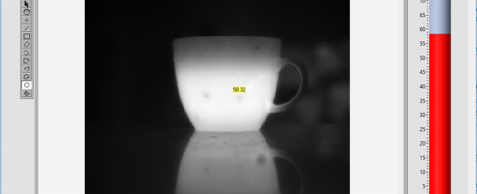
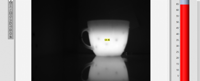
The above is a screenshot of the LabVIEW front panel. In the center is the image display, showing a black and white thermal image of a coffee mug. The brighter the intensity, the higher the temperature. The mouse cursor was placed in the center of the cup. The temperature is superimposed onto the image. The outside of the coffee mug is 64.46 degrees Celsius in this example. Also noticeable is that the image of the mug creates a reflection on the table surface. The surface is reflective in the long wave thermal band that the camera is sensitive to (8 to 14µm).

When you run the VI, it will connect to the camera. This assumes that the camera’s IP address and subnet mask matches the PC’s settings. Instructions on how to do this would go beyond the scope of this example. Once connected, you should see a thermal image after a few seconds. When you hover your mouse pointer over the image, it will display the temperature right next to it and also update the thermometer indicator to the right of the image.

Image Grab and Temperature Measurement from FLIR A35 A65 Using LabVIEW

BlockDiagram FLIR A35 A65 using LabVIEW

Here is how is works:

A: Open Camera VI
This VI will query attempt to connect to the selected camera. It will load the camera configuration file and create a unique reference to the camera.

B: Property Node
This property node configures the camera settings via GeniCAM as follows:

1) Pixel Format:
Sets the pixel format to either 8-bit or 16-bit. In this example, 16 bit format is chosen.

2) Sensor Gain Mode:
This will give the temperature value in 10mK from the camera.

3) Sensor Video Standard:
This attribute will set the frame rate of the camera. Currently, it is set to 50Hz.

C: IMAQdx Configure Grab VI
Sets the camera up for grabbing images.

D: IMAQ Create VI
Is used to create a reference in memory to store the images, streaming from the camera.

E: IMAQdx Grab2 VI
Is used to acquire the most recent frame from the given memory location.

F: IMAQ ImageToArray VI
Is used to convert the image to a 2D array.

G: This function converts from 10mK to Celsius (Note: this can be replaced to calculate the temperature to Fahrenheit)

H: This property node will extract the location of the mouse cursor in the image.

I: Index Array VI
Is used to extract the temperature at a given location of the mouse pointer and display it on the front panel.

J: IMAQ Clear Overlay VI
Is used to remove the previous overlay.

K: IMAQ Overlay Text VI
Is used to write the temperature value at the location of the mouse pointer.

L: IMAQ Dispose VI
Is used to clear the memory that was allocated to store the image.

M: IMAQdx Close Camera VI
Is used to close the unique reference that was created to communicate with the camera.


2024-08-30T15:55:52-07:00Thursday, March 21, 2024|Support|

How to grab an image from a FLIR A315 using LabVIEW

Grab an Image from a FLIR A315 Using Labview

How to grab an image and display the absolute temperature from the thermal camera FLIR A315 using LabVIEW from National Instruments.

The following instructions are intended to provide some beginner level advice and it is a “Hello World” example and a first step in how to capture a thermal image from a FLIR A315 using LabView. The FLIR A315 has a Gigabit Ethernet interface and supports the world-wide machine vision standard GeniCAM.

FLIR A315

Download the source code: FLIR_A315_using_LabVIEW.zip (206 KB)

Here is what you will need for this to work:

  • A PC with a LabVIEW development environment installed.
    • LabVIEW 2015 or later
    • NI Vision Development Module 2015 or later
    • IMAQdx 15.5 or later
  • FLIR A315 Thermal Camera connected to PC via Ethernet Cable
FrontPanel FLIR A315 using LabVIEW

The above is a screenshot of the LabVIEW front panel. In the center is the image display, showing a black and white thermal image of a coffee mug. The brighter the intensity, the higher the temperature. The mouse cursor was placed in the center of the cup. The temperature is superimposed onto the image. The outside of the coffee mug is 64.46 degrees Celsius in this example. Also noticeable is that the image of the mug creates a reflection on the table surface. The surface is reflective in the long wave thermal band that the camera is sensitive to (8 to 14µm).

When you run the VI, it will connect to the camera. This assumes that the camera’s IP address and subnet mask matches the PC’s settings. Instructions on how to do this would go beyond the scope of this example. Once connected, you should see a thermal image after a few seconds. When you hover your mouse pointer over the image, it will display the temperature right next to it and also update the thermometer indicator to the right of the image.

Image Grab and Temperature Measurement from FLIR A315 using LabVIEW

BlockDiagram FLIR A315 using LabVIEW

Here is how is works:

A: Open Camera VI
This VI will query attempt to connect to the selected camera. It will load the camera configuration file and create a unique reference to the camera

B: Property Node
This property node configures the camera settings via GeniCAM as follows:

1) Pixel Format:
Sets the pixel format to either 8-bit or 16-bit. In this example 16 bit format is chosen

2) IR Format:
This will give the temperature value in 10mK from the camera.

3) IR Frame Rate:
This attribute will set the frame rate of the camera. Currently it is set to 50Hz

4) Auto Focus:
This will send a trigger to the camera to auto focus on to an object

C: IMAQdx Configure Grab VI
Sets the camera up for grabbing images.

D: IMAQ Create VI
Is used to create a reference in memory to store the images, streaming from the camera

E: IMAQdx Grab2 VI
Is used acquire the most recent frame from the given memory location

F: IMAQ ImageToArray VI
Is used to convert the image to a 2D array

G: This function converts from 10mK to Celsius (Note: this can be replaced to calculate the temperature to Fahrenheit)

H: This property node will extract the location of the mouse cursor in the image

I: Index Array VI
Is used to extract the temperature at a given location of the mouse pointer and display it on the front panel

J: IMAQ Clear Overlay VI
Is used to remove the previous overlay

K: IMAQ Overlay Text VI
Is used to write the temperature value at the location of the mouse pointer

L: IMAQ Dispose VI
Is used to clear the memory that was allocated to store the image

M: IMAQdx Close Camera VI
Is used to close the unique reference that was created to communicate with the camera

2024-08-30T15:55:37-07:00Thursday, March 21, 2024|Support|

How to grab an image from a FLIR A615 using LabVIEW

Grab an Image from a FLIR A615 Using LabVIEW

How to grab an image and display the absolute temperature from the thermal camera FLIR A615 using LabVIEW from National Instruments.

The following instructions are intended to provide some beginner level advice and it is a “Hello World” example and a first step in how to capture a thermal image from a FLIR A615 using LabView. The FLIR A615 has a Gigabit Ethernet interface and supports the world-wide machine vision standard GeniCAM.

FLIR A615

Download the source code: FLIR_A615_using_LabVIEW.zip (257 KB)

Here is what you will need for this to work:

  • A PC with a LabVIEW development environment installed.
    • LabVIEW 2015 or later
    • NI Vision Development Module 2015 or later
    • IMAQdx 15.5 or later
  • FLIR A615 Thermal Camera connected to PC via Ethernet Cable
FLIR A615 LabVIEW Image Display Frontpanel

The above is a screenshot of the LabVIEW front panel. In the center is the image display, showing a black and white thermal image of a coffee mug. The brighter the intensity, the higher the temperature. The mouse cursor was placed in the center of the cup. The temperature is superimposed onto the image. The outside of the coffee mug is 64.46 degrees Celsius in this example. Also noticeable is that the image of the mug creates a reflection on the table surface. The surface is reflective in the long wave thermal band that the camera is sensitive to (8 to 14µm).

When you run the VI, it will connect to the camera. This assumes that the camera’s IP address and subnet mask matches the PC’s settings. Instructions on how to do this would go beyond the scope of this example. Once connected, you should see a thermal image after a few seconds. When you hover your mouse pointer over the image, it will display the temperature right next to it and also update the thermometer indicator to the right of the image.

Image Grab and Temperature Measurement from FLIR A615 using LabVIEW


The image below is the block diagram of the code that belongs to the front panel above.

LabVIEW FLIR A615 image grab block diagram

Here is how is works:

A: Open Camera VI
This VI will query attempt to connect to the selected camera. It will load the camera configuration file and create a unique reference to the camera

B: Property Node
This property node configures the camera settings via GeniCAM as follows:

1) Pixel Format:
Sets the pixel format to either 8-bit or 16-bit. In this example 16 bit format is chosen

2) IR Format:
This will give the temperature value in 10mK from the camera.

3) IR Frame Rate:
This attribute will set the frame rate of the camera. Currently it is set to 50Hz

C: IMAQdx Configure Grab VI
Sets the camera up for grabbing images.

D: IMAQ Create VI
Is used to create a reference in memory to store the images, streaming from the camera

E: IMAQdx Grab2 VI
Is used acquire the most recent frame from the given memory location

F: IMAQ ImageToArray VI
Is used to convert the image to a 2D array

G: This function converts from 10mK to Celsius (Note: this can be replaced to calculate the temperature to Fahrenheit)

H: This property node will extract the location of the mouse cursor in the image

I: Index Array VI
Is used to extract the temperature at a given location of the mouse pointer and display it on the front panel

J: IMAQ Clear Overlay VI
Is used to remove the previous overlay

K: IMAQ Overlay Text VI
Is used to write the temperature value at the location of the mouse pointer

L: IMAQ Dispose VI
Is used to clear the memory that was allocated to store the image

M: IMAQdx Close Camera VI
Is used to close the unique reference that was created to communicate with the camera

2024-08-30T15:53:05-07:00Thursday, March 21, 2024|Support|

What is NETD in a Thermal Camera?

NETD in a Thermal Camera

NETD explained

You may come across the expression or specification of “NETD” when you look at the technical details of a thermal camera. The expression stands for “Noise Equivalent Temperature Difference”. It is a measure for how well a thermal imaging detector is able to distinguish between very small differences in thermal radiation in the image. NETD is typically being expressed in milli-Kelvin (mK). It is also sometimes referred to as “Thermal Contrast”. When the noise is equivalent to the smallest measurable temperature difference, the detector has reached its limit of its ability to resolve a useful thermal signal. The more noise there is, the higher the NETD value of the detector.

Typical values for uncooled, micro-bolometer detector thermal cameras are on the order of 45 mK. Scientific cameras with photon based and cryogenically cooled detectors can achieve NETD values of about 18 mK. The noise measurement value should be specified at a particular object temperature, as this impacts the measurement. Example: NETD @ 30C : 60 mK

How is NETD being measured?

In order to measure the noise equivalent temperature difference of a detector, the camera must be pointed at a temperature controlled black body. The black body needs to stabilize before starting the measurement. The noise equivalent temperature difference is then being measured at a specific temperature. It is not a single snapshot measurement, but rather a temporal measurement of noise.

The image on the left shows a noisy thermal image that the camera produces when looking at a very uniform black body during the measurement. The image on the right shows a histogram of all pixel values taken from several images over time. It is a temporal distribution of noise at that temperature. The NETD value is the standard deviation of that histogram (STDEV) converted into mK.

How does NETD affect the measurement?

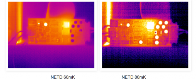
The images below show the same scene recorded by two different cameras. One camera has an NETD of 60 mK and the second has value of 80 mK. The areas in the image with very low temperature show significantly more noise in the image taken with the 80 mK camera. 20 mK difference doesn’t seem like much, but it has a potentially huge impact on the image quality and measurement accuracy.

NETD thermal image comparison

What affects NETD?

Several factors can affect NETD. Thermal cameras sometimes come with more than one calibrated temperature measurement range. The noise reading can vary based on the selected range and also the object temperature. As long as there is significant thermal contrast in the image and the temperature of interest is a lot higher than the background temperature, then this won’t affect the measurement accuracy much. The noise level can also be affected by the detector and/or camera temperature. If the camera is exposed to a high ambient temperature, the system noise may increase. This depends on how well the camera is internally stabilized. The effects of this internal temperature drift can be observed in between non-uniformity calibrations or ‘NUCs’, which can be several minutes apart. Another variable that can affect NETD is the #f-stop of the lens. The #f-stop or aperture of the lens determines how my thermal radiation reaches the detector. Generally, a lower #f-stop will lead to a better noise value.

Do you have more questions? Are you working on an application that might benefit from thermal imaging? Let us know! Chat with us! Contact us to talk with an engineer!

2024-08-16T17:29:15-07:00Thursday, March 21, 2024|Blog|

Semiconductor Failure Analysis Using Thermal Imaging

Semiconductor Failure Analysis Using Infrared NDT

Solar Cell Lock In Electroluminescence NDT Solutions

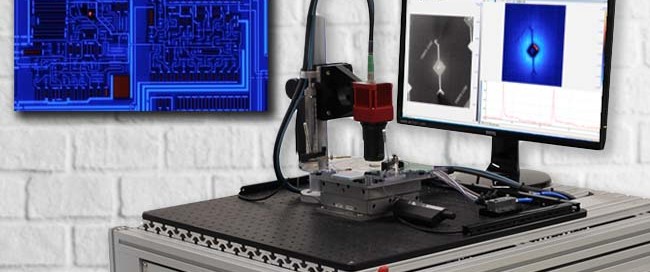
MoviTHERM’s Semi-CHECK solutions allows the detection of shorts and other defects in semiconductors. This system uses a FLIR Thermal camera with microscopic lens attachment in order to provide the correct magnification. Lockin Thermography allows to detect defects with nano-watt to micro-watt signatures.

More info about MoviTHERM Semi-Check

Download Our Starter Guide

For Infrared NDT Systems

Infrared Non-destructive Testing Guide
  • Learn how Infrared NDT works

  • Learn what type of defects you can find

  • Learn how large of an area you can inspect

  • Learn how this method compliments UT inspections

  • Learn how to save valuable inspection time

2024-08-16T17:29:25-07:00Thursday, March 21, 2024|Blog|

Solar Cell Lockin Electroluminescence

Solar Cell Lockin Electroluminescence Using Infrared NDT

Solar Cell Lock In Electroluminescence NDT Solutions

MoviTHERM’s Solar-CHECK solution allows for inspection of solar cells. This particular method examines the electroluminescense when using electrical excitation of the cell.

Download Our Starter Guide

For Infrared NDT Systems

Infrared Non-destructive Testing Guide
  • Learn how Infrared NDT works

  • Learn what type of defects you can find

  • Learn how large of an area you can inspect

  • Learn how this method compliments UT inspections

  • Learn how to save valuable inspection time

2024-08-16T17:29:36-07:00Thursday, March 21, 2024|Blog|

What is Lock-In Thermography?

Lock-In Thermography NDT Technique

The principle of lock-in thermography is based on the application of a periodic input energy wave (i.e. thermal emitter, ultrasound, microwave, eddy current, flash or xenon lamp, halogen lamp, or laser) to the surface of the object being examined and analyzing the resulting local temperatures on the surface of the object.

When the input energy wave penetrates the object’s surface, is it absorbed and phase shifted. When the input wave reaches areas within the object where the thermophysical properties are not homogeneous in relation to the surrounding material, (i.e. at delaminations or inclusions), the input wave is partially reflected.

The reflected portion of the wave interferes with the incoming input wave at the surface of the object, causing an interference pattern in the local surface temperature, which oscillates at the same frequency as the thermal wave.

The internal structure of the object being examined can then be derived by evaluating the phase shift of the local surface temperatures in relation to the input energy wave. The ability to derive internal thermophysical inconsistencies within the object, however, requires that the input energy source be used at an optimal frequency, which depends on both the thermophysical characteristics of the object as well as its thickness.

Lock-In Thermography

The principle measurement setup is shown here.

MoviTHERM Lock-In Thermography NDT Solution

MoviTHERM Lockin Thermography Non-Destructive Test System. This system is a Lockin Thermography System used for defect detection in materials, such as composites, metals and non-metals. Lockin Thermography allows the detection of some very weak signals even below the noise floor of the camera in the micro-Kelvin range. This ability makes this method the perfect candidate for locating tough to find material defects.

In this video we explain the application of the Lock-In Thermography method using a FLIR camera and an irNDT system.

Download Our Starter Guide

For Infrared NDT Systems

Infrared Non-destructive Testing Guide
  • Learn how Infrared NDT works

  • Learn what type of defects you can find

  • Learn how large of an area you can inspect

  • Learn how this method compliments UT inspections

  • Learn how to save valuable inspection time

2024-08-16T17:29:45-07:00Thursday, March 21, 2024|Blog|
Go to Top