About MoviTHERM

This author has not yet filled in any details.
So far MoviTHERM has created 157 blog entries.

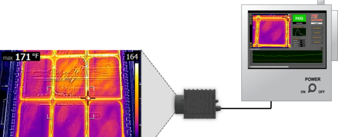
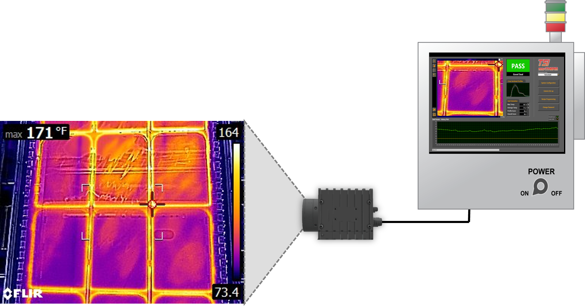
Packaging Seal Integrity Ensured Using Infrared

Ensuring Packaging Seal Integrity with Infrared Inspection

Package seal integrity is critical for today’s manufacturers. For example, in the food and beverage space, faulty packaging limits the shelf life of a product. This increases waste, especially for perishable items where package leaks accelerate the decomposition process. For the pharma and health industries, package sterility ensures product efficacy and safeguards end users.

As part of a quality control program, companies randomly sample packages and conduct leak tests on package seals. A typical test method involves placing the package in a vacuum chamber and submerging in water. As internal pressure builds in the package, leaks become visibly detectable by the presence of escaping air as bubbles. While effective at detecting leaks on a single test sample, this approach is laborious and only addresses some packages produced.

Over the past twenty years, infrared (IR) camera technology developments have made IR cameras more rugged, smaller in size, and less expensive. New applications for infrared cameras and non-contact temperature measurement are continually developing as the technology becomes more assessable.

Automating infrared inspection for package seal integrity testing is one application that continues gaining traction. Using infrared inspection as part of a quality control program allows for inspecting all package seals in the production line. Companies can ensure package seal integrity, promote product quality, and elevate customer satisfaction by implementing complete package line inspection.

Infrared image of a pouch seal. The image on the left is a good seal. The one on the right is bad. The area plot below the IR images shows the numerical results.

Infrared images of a pouch seal.

The example on the left is a good seal. The example on the right is a bad seal. The area plot below the IR images shows the numerical results.

MoviTHERM TSI for Package Seal Integrity Inspection

MoviTHERM TSI is a package seal integrity inspection system that leverages infrared imaging to assess the quality of heat-based package seals. Infrared cameras “see” the residual heat from joining, gluing, and sealing processes. The automated inspection system compares unknown package seals to known good seal profiles and reliably detects good and bad seals. MoviTHERM TSI has an integrated recipe manager that allows the system to store hundreds of inspection scenarios. The system also allows for system adaptation to various packaging seal inspection applications.

Core features of MoviTHERM TSI include:

  • Infrared Cameras that view and measure thermal variations of good and bad seals without contact.
  • Hardware and software that easily integrates with existing production equipment
  • Advanced and reliable inspection logic pre-programmed for multiple packaging scenarios.
  • Image and data logging for traceability of performance.
  • Optional cloud-based connectivity that keeps key production personnel always in the know.
  • And most importantly, peace of mind, knowing that your products and being appropriately packaged and customers are happy.

Infrared Inspection is Key

The critical component of the TSI solution is infrared imaging which allows the system to see the heat from the package sealing process. Some important points regarding infrared light/infrared radiation:

  • All objects above absolute zero emit infrared light/radiation (that’s -273 degrees C or -460 degrees F).
  • The only difference between visible light (the light we see) and infrared light is the wavelength size. (shown in the chart below)
  • As such, infrared light behaves similarly to visible light in that it can be reflected, absorbed, and transmitted through an object.
  • The human eye is tuned to see a tiny sliver of all the light forms in the universe.
Electromagnetic Spectrum Chart

Electromagnetic Spectrum Chart

Infrared (IR) cameras operate on the heat transfer principle of radiation. The IR camera has a focal plane array of detector elements that sense infrared light from object surfaces. The radiation captured by the IR camera detector is digitized, converted to data, and displayed as a viewable image.

Calibrated IR cameras can report temperature measurements from specific spots, lines, and areas on live or recorded images. IR cameras are available in different wavebands, pixel resolutions, lens configurations, and communication protocols to meet various installation requirements.

Infrared Camera Viewing a Heated Bottle Cap Seal

Infrared Camera Viewing a Heated Bottle Cap Seal

MoviTHERM TSI Inspection Software

The following is a sample view of the TSI user interface. All buttons and features are touch screen accessible. In this example, we are inspecting bottle caps. The bright yellow ring in the thermal image indicates a good seal, as indicated by the green “PASS” in the indication window.

TSI Software Display

TSI Software Display

Package Seal Integrity Applications

TSI is an effective inspection solution for inspecting bags sealed with heat. Bags leaving the heated press or sealed with hot glue retain a residual heat that can be detected and inspected with TSI.

MoviTHERM TSI for Bag Seal Integrity Inspection

MoviTHERM TSI for Bag Seal Integrity Inspection

Already discussed is TSI for Bottle Cap inspection. In this example, an induction sealer creates heat in the foil section of the sealing packet. The residual heat from the heating process can be evaluated for seal condition and fault type if one is present.

MoviTHERM TSI for Bottle Cap Seal Integrity Inspection

MoviTHERM TSI for Bottle Cap Seal Integrity Inspection

TSI can be used to evaluate the seams formed by heat and pressure in pouch-forming processes. TSI detects leaks in pouches by comparing the thermal profiles of test samples to the seam profiles of known non-leakers.

MoviTHERM TSI for Pouch Seal Integrity Inspection

MoviTHERM TSI for Pouch Seal Integrity Inspection

Thin film plastic covered packages are commonplace in the food industry. TSI quickly and reliably identifies the seal area to detect seal integrity, ensuring that food products are safe for consumers.

MoviTHERM TSI for Package Seal Integrity Inspection

MoviTHERM TSI for Package Seal Integrity Inspection

What’s Included with MoviTHERM TSI for Package Seal Integrity Inspection?

MoviTHERM TSI solution for automated seal integrity inspection provides 100% in-line, high-speed integrity inspection for heat-related production lines. Each product and packaging is inspected using infrared imaging and advanced machine vision analysis. The system includes:

  • High performance infrared camera
  • Standard powder-coated Industrial Electrical Enclosure (Optional Stainless-Steel enclosure for food & beverage or pharmaceutical environments)
  • Touch-Screen PC and application specific software GUI interface
  • Interactive inspection Recipe Programmer to accommodate multiple products – or to try different “what-if” scenarios
  • Robust bi-directional PLC interface to transfer status messages and PASS/FAIL results to a plant PLC (Ethernet/IP or Modbus)
  • Image FTP to transfer fault images to a remote server for off-line review
2024-08-16T17:22:05-07:00Thursday, March 21, 2024|Blog|

Passive vs Active Thermography

What is the difference between Passive vs Active Thermography?

If you ask someone what infrared is, they’d probably say “it’s the technology used in night vision goggles and gun sights”. While this might be true, there is more to it. IR produces temperature differences that are readable by cameras. In this article, we explain the basics of infrared thermography and break down the difference between passive and active thermography and its different use cases and methods.

Infrared Light, Detectors, & Cameras

Infrared light, or infrared radiation, is always around us. We just can’t see it. In fact, all objects above absolute 0 (- 273 degrees C or – 460 degrees F) emit infrared light. So not only do hot and warm objects emit infrared light, but also cold objects like a bucket of ice cubes. The amount of infrared light emitted from an object is proportional to the temperature of that object. For example, a campfire emits more IR light than a lantern and significantly more IR light than a bucket of ice.

Electromagnetic Spectrum

The electromagnetic spectrum is a term scientists use to describe the entire range of light. The following chart graphically represents the electromagnetic spectrum and shows the various forms of light, from radio waves to microwaves and x-Rays to gamma rays. What’s interesting to note is that most of the electromagnetic spectrum is invisible to us, including infrared light. From the chart, we see that only a tiny sliver of the light available in the universe is visible to us.

Electromagnetic Spectrum MoviTHERM

The Electromagnetic Spectrum

Also, from the electromagnetic spectrum chart, we see infrared light has a larger wavelength than visible light. Because it is only different in size, infrared light behaves similarly to visible light. For example, infrared light can be absorbed, passed through, and reflected like visible light.

While our human eye is not tuned to see infrared light, there are semiconductor materials that can sense it. By organizing these materials into a matrix of rows and columns and combining them with microelectronics, engineers have developed focal plane array (FPA) infrared detectors.

Infrared Detectors

Infrared detectors are made with materials like Amorphous Silicon, Vanadium Oxide, Indium antimonide, Indium Gallium Arsenide, and Mercury Cadmium Telluride. They come with various pixel sizes, numbers of pixels, and infrared sensing wavebands. For example, there are shortwave infrared (SWIR), midwave infrared (MWIR), and longwave infrared (LWIR) detectors that “see” infrared light in those infrared regions. Infrared FPA detectors can range in pixel resolutions from 60 x 80 (4,800 pixels) up to 1280 x 1024 (1.3 megapixels).

When integrated into a camera with an infrared lens, IR FPA detectors capture the focused infrared light that is converted into an electronic signal and presented as grayscale or colorized images. Each pixel of the infrared image represents a digitized level of infrared light. You can visually identify the image’s cold, warm, and hot areas with a corresponding grayscale or color scale palette. One can easily pick out the white-hot engine cylinders and exhaust outlets in the following infrared image of a motorcycle.

Example IR Image Motorcycle with Regions of Interest

Example IR Image Motorcycle with Regions of Interest

Regions of Interest (ROI’s)

If the infrared camera is calibrated for temperature measurement, tools called regions of interest (ROI), can be applied to the live or recorded image. Images present average, minimum, and maximum temperature values. ROI’s typically include spots, lines, and areas. Because the thermal image is made up of several thousand spot measurements, temperature values can be presented from any one of the image pixels.

What is Thermography?

Thermography is the practice of using an infrared camera to see and/or measure the thermal characteristics of an object or process to assess its condition as related to temperature.

For example, during the recent Corona Virus pandemic, thermography was conducted on people to detect elevated body temperatures. Thermography was used as a pre-screening tool to identify individuals who may have a fever, a potential indicator of infection.

Another example of infrared thermography includes inspecting connections in a substation to ensure electricity flows freely. Typically, with an increase in resistance to the flow of electricity, there is a corresponding increase in heat. The increased electrical resistance could result from a loose connection, corrosion, or component failure. Regardless of the cause, increases in resistance produce rise of heat that can be seen and measured with an infrared camera.

The relationship between heat and electrical resistance can also apply to microelectronics, like looking for shorts on a printed circuit board that could shorten the life of a laptop. Other examples of thermography include:

  • Looking for cold spots in buildings to identify areas of missing insulation.
  • Looking for increased temperature in rotating equipment caused by the friction of a possible bearing failure.
  • Observing how heat flows through the wing of an aircraft to reveal the presence of water.

What is Passive Thermography?

Passive thermography relies upon the naturally occurring thermal light emitted from an object or process for condition evaluation. With passive thermography, thermal contrast is only observed with an infrared camera if the target’s temperature differs from the ambient temperature or surrounding objects. The resulting thermal image will show little variation in color or greyscale if there is no thermal contrast.

Any temperature distribution of the object or scene is evaluated without imposing external energy on the object. The observed temperature patterns are due solely to the inherent temperature differences.

Examples of passive thermography include the electrical substation, and microelectronics inspection discussed previously. Other examples include the inspection of a motor to be sure it is cooling properly or inspecting electrical relays to ensure they are working correctly. Each of these inspection examples relies upon the presence of a variation in temperature or variation of emitted infrared light resulting from the normal operation of the process.

Example IR Image Motorcycle with Regions of Interestpassive thermography inspection on electrical relays

What is Active Thermography?

Active thermography is applying external energy sources to an object or process to induce a variation in temperature for analysis with an infrared camera. Active thermography can be a viable nondestructive test method for objects or scenes with no naturally occurring thermal variation. In other words, no naturally occurring temperature differences exist in the object or scene.

Inspecting the wing of an aircraft with a thermal camera

Passive Thermography: Inspecting the wing of an aircraft with a handheld thermal camera.

Suppose we want to evaluate an aircraft wing for the presence of defects. If observing the wing at a steady state with an infrared camera, we would likely see little to no thermal contrast in the resulting IR image. However, if we applied external energy to the wing, like heat from a halogen lamp, we could observe how the thermal wave from the lamp travels through the wing over time.

Using an external excitation source to detect defects in the object of interest

Active Thermography: Using an external excitation source to detect defects in the object of interest.

If a defect is present inside the wing, it interrupts the heat flow from the halogen lamp, causing a variation in the temperature distribution at the object’s surface. This variation is viewable with an infrared camera.

Detecting defects of an object using a thermal camera and an excitation source (halogen lamp).

Detecting defects of an object using a thermal camera and an excitation source (halogen lamp).

One example of active thermography is using a halogen lamp to induce a thermal wave across a wing. Additional excitation sources for active thermography include:

  • Xenon Flash lamps for creating short, high-intensity heat waves.
  • Ultrasonic Vibration Horns induce mechanical friction at cracks and disbonds, causing heat.
  • Induction coils for creating eddy currents that produce localized heat when blocked by defects.
  • Programmable power supplies for introducing current into semiconductors and electronics that heat up when shorted or resisted.
  • Lasers for applying pinpoint heat to small targets like microelectronics.

Inspection systems for active thermography typically use a computer to record the object’s surface temperatures as a function of time. These infrared videos are processed using software designed to “tease out” defects and anomalies that go unnoticed with passive thermography.

Various techniques for active thermography are available to conduct the most effective testing for a specific material or device. Listed below are six different types of active thermography testing techniques that are commonly used today.

Transient

Halogen light is used to create an extended heat excitation. Thermography analyzes the change in the thermal state of the target.

Flash or Pulse Thermography

Xenon light provides a short and intense excitation that is analyzed with thermography. Is well suited for materials with high thermal conductivity and shallow defects. Read our article on flash thermography to learn more.

Lock In Thermography

A periodical excitation source is synchronized with the IR camera. The software generates an amplitude and phase image to indicate the location and nature of the defect. Read our article on lock-in thermography to learn more.

Vibro Thermography

Ultrasound is used to excite the specimen. Friction between vibrating cracks creates heat signatures measured by the infrared camera. Read our article on vibro thermography to learn more.

Failure Analysis

A test specimen is excited with a periodic electrical signal and a synchronized thermal camera captures the resultant surface temperatures. Processing algorithms produce a surface map identifying localized hotspots.

Thermal Stress Analysis (TSA)

A test sample is stressed by modulating mechanical excitation with the induced infrared imagery converted into stress units.

Applications for active thermography include finding disbonds in aluminum structures like on an aircraft fuselage or seeing corrosion behind painted surfaces. Additional applications include identifying failure points in microelectronics, evaluating laser weld penetration, and visualizing wheel cracks. These are just a few of the many applications of active infrared thermography.

Finding Disbonds in Aluminum Structures

Finding Disbonds in Aluminum Structures

Identifying Failure Points in Microelectronics

Identifying Failure Points in Microelectronics

Evaluating Laser Weld Penetration

Evaluating Laser Weld Penetration

Inspecting Wheel Cracks with Infrared

Inspecting Wheel Cracks with Infrared

Passive vs Active Thermography

Passive thermography is the use of infrared cameras or other devices for measuring the temperature of a surface. In passive thermography, the temperature of an object is measured without direct contact. The radiation emitted by an object is captured by a camera, and the temperature information is extracted from the image. Passive thermography does not require any active illumination (such as lights) or specialized equipment, making it extremely useful for inspections in dark or enclosed spaces.

Active thermography is the use of emitters to illuminate objects with infrared light and then take images using an infrared camera. The advantage of active thermography over passive thermography is that it can detect defects that might not be visible using other testing methods, including passive thermography.

Both active and passive thermographic inspections can be performed on a wide range of objects including turbines and generators, aircraft engines, electrical panels, motors, transformers and generators, HVAC systems and much more.

Download Our Starter Guide

For Infrared NDT Systems

Infrared Non-destructive Testing Guide
  • Learn how Infrared NDT works

  • Learn what type of defects you can find

  • Learn how large of an area you can inspect

  • Learn how this method compliments UT inspections

  • Learn how to save valuable inspection time

2024-08-16T17:22:16-07:00Thursday, March 21, 2024|Blog|

Different Types of Non-Destructive Testing (NDT)

The Top 9 Different Types of Non Destructive Testing

What is Non-Destructive Testing?

Non-destructive tests (NDT) are methods that do not damage the parts being tested. NDT uses various inspection techniques to assess individual or group components. By employing different principles from physics, chemistry, and mathematics, NDT can test components without causing damage.

NDT can also be referred to as non-destructive evaluation/examination (NDE) or non-destructive inspection (NDI).

Types of Non-Destructive Testing Methods

Below are 9 common types of non-destructive testing being used today:

1. Thermal/Infrared Testing

movitherm battery inspection ndt

Flash Thermography for Battery Inspection

Infrared Non-Destructive Testing has been around for more than 30 years, but has recently gained more momentum. Infrared non-destructive testing is based on the principle of thermal wave imaging. It is considered an active thermography method, as opposed to a passive method.

The active part comes from using an external heat source to warm up the part. Whereas in standard thermography, the camera is usually capturing heat, inherent to the process.

Examples of Thermal/Infrared Inspections:

Finding disbonds in aluminum structures like on an aircraft fuselage or seeing corrosion behind painted surfaces. Other examples include: identifying failure points in microelectronics, evaluating laser weld penetration, and visualizing wheel cracks.

2. Radiography Testing

Radiographic Testing (Image Source)

Radiographic testing (RT) uses X-radiation or gamma radiation to find imperfections in a component or system. An X-ray generator or radioactive isotope is used to send radiation into the material being tested. The radiations are then caught by a detector. The resulting shadowgraph is then used by inspectors to look for potential issues.

Example of Radiography Inspections:

X-rays and CT scans can be used in industrial radiography to see detailed images of the tested material.

3. Visual Inspections

Visual Checks

Visual testing is a way of checking the condition of a material by looking at it. This is the most basic form of testing, and you can do it just by looking at the material. For more detailed visual inspections, you can use a Remote Visual Inspection device to get a closer look.

Example of Visual Testing:

Maintenance professionals use the visual testing method on a daily basis to check for common signs of wear and tear on industrial machinery.

4. Leak Testing

Leak Testing – Bubble Test

Leak testing is used to study leaks and identify defects in structures or vessels. Inspectors often use soap-bubble examinations, pressure gauges, and listening devices to conduct leak testing.

Example of Leak Testing:

A good example of leak testing is using it to find leaks in sealed packaging or devices that do not include an opening for filling.

5. Acoustic Emission Testing

Diagram of Accoustic Emission testing

Accoustic Emission Testing (Image Source)

Acoustic emission (AE) testing uses acoustic emissions to identify potential defects in an asset. This testing involves looking for acoustic energy bursts, as these bursts indicate defects. The arrival time, location and intensity of a burst are also examined to identify potential issues.

Example of Acoustic Emission Testing:

AE testing is commonly used to inspect structures such as pressure vessels, pipelines, storage tanks, aircraft structures and steel cables for any defects.

6. Ultrasonic Testing

Diagram explaining ultrasonic testing

Ultrasonic Testing

Ultrasonic testing uses high-frequency sound waves to detect and evaluate flaws, measure dimensions, and characterize materials. It is performed with an ultrasonic receiver and transmitter.

Example of Ultrasonic Inspections:

Ultrasonic testing can be used to identify defects and deformation in the wheels and axles of railway carriages.

7. Magnetic Particle Inspection

image example of magnetic particle inspection

Magnetic Particle Inspection (Image Source)

Magnetic particle testing is a process of detecting flaws in a material by observing disruptions in the flow of the material’s magnetic field. To carry out these tests, an inspector first induces a magnetic field in a magnetically susceptible asset. They then sprinkle iron particles over the surface of the material. These particles will reveal any disruptions, providing a visual indication of where the imperfections are located.

Examples of Magnetic Particle Testing:

A good example of magnetic particle testing is using it to inspect the internal and external surfaces of boiler and pressure vessels.

8. Liquid Penetrant Testing

Liquid Penetrant Testing Example

When conducting liquid penetrant testing, an inspector will apply a coating of liquid with a fluorescent or visible dye to an asset. They will then remove any excess solution from the surface of the asset. The remaining solution is left in any breaks or defects in the surface. These defects will be revealed by the dye, which can then be removed using ultraviolet light. With regular dyes, inspectors will study defects by the contrast between the developer and penetrant.

Example of Liquid Penetrant Inspection:

A good example for penetrant testing can be used for inspecting weld metal build-up on plates.

9. Eddy Current Testing

diagram example of eddy current testing

Eddy Current Testing (Image Source)

Eddy current testing is a form of electromagnetic testing where inspectors measure the strength of eddy currents (electrical currents) in a material’s magnetic field. By looking for interruptions in the current, inspectors can often spot defects in the asset or material.

Examples of Eddy Current Testing:

This type of test method can be used for surface scanning, subsurface inspection, weld inspection, fastener hole inspection, tube inspection, heat treatment verification, and metal grade sorting.

What industries use NDT?

Many different industries utilize different types of non-destructive testing to ensure their materials, systems and assets are in good condition and free from defects. For example, companies employing manufacturing and fabrication processes often use NDT to ensure products have the required reliability and integrity. Those in manufacturing also use NDT to keep their products consistent and better control their manufacturing processes.

Non-destructive testing is used for condition assessment and quality control in a wide range of industries, which include (but are not limited to):

  • Mining
  • Automotive
  • Oil and gas
  • Medical Devices
  • Aerospace
  • Maritime
  • Military and defense
  • Power generation
  • Manufacturing
  • Packaging
  • Waste Management

Turn to MoviTHERM for Infrared Non-Destructive Testing Solutions

MoviTHERM provides infrared NDT solutions to help engineers, researchers, and developers solve problems that cannot be resolved with traditional passive infrared test methods. MoviTHERM’s irNDT solutions use active excitation and intelligent algorithms to tease out the finest internal details of a material.

Find out more about MoviTHERM’s infrared non-destructive testing solutions today. If you have any questions, please feel free to contact us.

Download Our Starter Guide

For Infrared NDT Systems

Infrared Non-destructive Testing Guide
  • Learn how Infrared NDT works

  • Learn what type of defects you can find

  • Learn how large of an area you can inspect

  • Learn how this method compliments UT inspections

  • Learn how to save valuable inspection time

2024-08-16T17:22:26-07:00Thursday, March 21, 2024|Blog|

Industrial Fires: The 5 Common Causes

The 5 Common Causes of Industrial Fires

Loss prevention is always a top priority for most businesses and industries. One of the most devastating losses is an industrial fire.

According to the National Fire Protection Association (NFPA), an average of 37,000 fires occur yearly at industrial and manufacturing properties. The number of fatalities is extremely limited – just one or two deaths per year on average. However, the costs for loss of inventory and damages make up around $500 million in a year.

Below are the five main causes of industrial fires to help manage risk:

1. Combustible Dust

Combustible dust is a common cause of fire in industrial facilities. This can include dust from metal or coal processing, or even sawdust.

This type of fire occurs when combustible dust is suspended in the air instead of being allowed to settle on a surface. When this happens, the dust particles can ignite and cause an explosion. Once it has been ignited, the fire will spread quickly as it is spread by air currents in the building.

How to prevent combustible dust fires?

  • Inspect for dust regularly, especially in hidden areas.
  • Use a dust collection system to avoid buildup.
  • Use cleaning methods that won’t create dust clouds.
  • Control smoking, open flames, and sparks.

2. Hot Work

Hot work is a term used in the industry to describe processes that involve heating and welding materials. This type of work often produces sparks, which can ignite flammable materials nearby.

How to prevent hot work fires?

  • Train employees in safety procedures.
  • Provide employees with proper safety equipment.
  • Clear work area of any flammable materials, including dust, gases, and liquids.

3. Flammable Liquids and Gases

This is the most common cause of industrial fires, accounting for about 40% of all incidents. Many flammable liquids are used in manufacturing processes, including diesel fuel and gasoline. These fuels can cause fires if they leak or if they are spilled on hot machinery or equipment.

How to prevent flammable gas fires?

  • Be familiar with the risks of each flammable liquid and gas on-site.
  • Read and follow the safety information for storage, and consult the material safety data sheet that comes with the product.
  • Store hazardous materials properly, in accordance with OSHA standards.
  • Keep ignition sources away from flammable gases and liquids.
  • Provide employees with personal protective equipment as needed.

4. Equipment and Machinery

Equipment malfunctions are another common cause of industrial fires. Furnaces, boilers, and related heating equipment all have the potential to ignite when not maintained properly.

How to prevent equipment fires?

  • Train employees on how to identify possible risks and what to do if they find one.
  • Keep machines, equipment, and areas surrounding them, clean and clear of flammable materials.
  • Prevent machine overheating by following guidelines for recommended maintenance procedures.

5. Electrical Hazards

Electrical fires include wiring that is exposed or not up to code, overloaded outlets, extension cords, overloaded circuits, or static discharge.

How to prevent electrical fires?

  • Don’t overload electrical equipment or circuits.
  • Unplug temporary equipment not in use.
  • Avoid using extension cords.
  • Use antistatic equipment as advised by OSHA and NFPA.

Prevent Fires and Explosions

A fire is a dangerous situation that can be difficult to get under control and stop. Sometimes following all proper safety guidelines isn’t enough to prevent a disastrous loss. Intelligent early fire detection systems such as, MoviTHERM’s iEFD, detects fire before the appearance of smoke, giving employees time to respond quickly and put out the blaze before it causes any real damage.

20+ Page Guide to Fire Detection Systems

Find All Your Answers in Our Guide

Infrared Non-destructive Testing Guide
  • Find a reliable fire detection system.
  • Save money in the long run.

  • Know the must-have features.
  • Find a system that adapts to your business needs.

  • Understand the importance of safety and security.
2024-08-16T17:22:34-07:00Thursday, March 21, 2024|Blog|

Composite Inspection Solutions Using Infrared Imaging

Using Infrared Imaging for Composite Inspection

How is thermal imaging used in composite inspection solutions?

Composite honeycomb

Honeycomb material with a lock-in result image shows circular delaminations, circled in red.

In this article, we break down the four subcategories of infrared nondestructive testing for the use of composite inspection solutions.

The first documented use of composite materials was most likely in ancient Egypt during the time of the Pharaohs. Workers were using straw and mud to make building materials. When talking about composite materials today, one usually refers to advanced materials used either in aerospace, military, and racing or automotive applications. Recently, one of the biggest boosts for using composite materials has been commercial aircraft manufacturers such as Boeing with the Dreamliner B-787 and Airbus with the A350.

airbus a350

The Airbus A350 has been designed with more than 50% composite materials. Source: Airbus

In an attempt to make these super liners more fuel efficient, both companies have designed more than 50% of these aircrafts out of composite materials. With these large scale composite structures also comes a significant need for nondestructive material testing (NDT), both for manufacturing as well as in-service inspection.

Traditionally, this need has been fulfilled with ultrasound NDT. However, many parts for these aircraft are being manufactured with complex shapes and curvatures, making it difficult or impractical to use ultrasound sensors which need to be positioned true (orthogonal) to the surface of the material being inspected.

Thermal imaging is not as widespread as ultrasound inspection in the NDT world, although it has many advantages when it comes to large scale composite materials with complex shapes. Thermographic NDT techniques fall into the category of active thermography, due to use of an active heat excitation source. There are four subcategories of thermal or infrared (IR)-NDT that are used for composite inspection solutions: flash, transient, vibro-thermography and lock-in thermography.

Flash Thermography

Flash, sometimes also called pulse thermography, uses a very short pulse of energy, such as provided by a Xenon flash lamp, as the active excitation for the measurement. An infrared or thermal camera is then used to record an image sequence of the heat up and cool down period of the material.

turbine blade show micro-cracks

The orange spots on this lock-in image result image of a turbine blade show micro-cracks, some beneath the surface.

When observing the thermal wave on the surface of the material during this period, defects such as impact damages, voids, foreign material inclusions, disbands and water inclusions manifest themselves with their varying thermo-physical properties compared to the intact or defect-free material.

These thermo-physical differences create disturbances or interferences in the surface thermal wave, which the thermal camera records. These image sequences can contain up to multiple hundreds of thermal images. The analysis software then calculates a result image that based on the applied algorithm may be displayed as a phase angle image.

Vibro-Thermography

In a vibro-thermography system, induced ultrasound waves are used to create friction and therefore heat on crack surfaces inside or on the surface of the material. This friction heat can then be seen with the help of the thermal camera. Typical applications for such a vibro-thermography system are the inspection of ceramics and metals for cracks and micro-cracks.

Lock-In Thermography

The principle measurement setup is shown here.

Lock-In Thermography

One of the more sophisticated thermal NDT methods available is lock-in thermography. A typical measurement setup for composite NDT using a lock-in thermography system usually involves halogen lamps for excitation.

The underlying principle is based on “locking in” the camera recordings on the known excitation frequency. The sample materials can thereby be excited continuously by using a sinusoidal waveform for modulation of the halogen lamp or lamps. This has the distinct advantage that the heat or thermal wave never decays to the point where the camera can no longer pick up the heat signature.

For instance, with flash or transient thermography a singe and finite heat pulse is used for excitation. The collection of useful thermal images ends at the latest, when the amplitude of the thermal wave approximates the noise floor of the camera detector. This in turn limits the maximum achievable penetration depth of the measurement. This is particularly critical in composite materials, which usually do not conduct heat as well.

Lock-in thermography uses Fast Fourier Transform (FFT) algorithms for calculation of the result image. The image data is evaluated on a pixel-by-pixel basis in the frequency domain and it only allows for signals to be evaluated that are an exact frequency match to that of the excitation source, thus eliminating undesirable thermal reflections.

In fact, since the frequency of noise of the measurement system is random, this method allows for an increase of the thermal sensitivity that reaches below the noise floor of the camera itself. This significantly improves the signal-to-noise (SNR) ratio of a lock-in thermography system, allowing for detection of tough-to-find defects, compared to IR-NDT methods.

The typical thermal sensitivity of a cooled IR-camera is around 25 millikelvin (mK). A lock-in thermography system can extend that range down to the µK range, or by a factor of 100 to 1,000.

Other application examples for using lock-in thermography are thermal stress analysis for nondestructive evaluation of material strengths and shunt detection for photovoltaic (solar) cells and panels.

Download Our Starter Guide

For Infrared NDT Systems

Infrared Non-destructive Testing Guide
  • Learn how Infrared NDT works

  • Learn what type of defects you can find

  • Learn how large of an area you can inspect

  • Learn how this method compliments UT inspections

  • Learn how to save valuable inspection time

2024-08-16T17:22:45-07:00Thursday, March 21, 2024|Blog|

IR Cameras Prevent Recycling Plant Fires

Preventing Recycling Plant Fires with IR Cameras

With more lithium-ion batteries and other flammable materials ending up in consumer waste, recycling plant fires are becoming more common than they should.

In the last year alone, there were over three hundred reported fire incidents in the waste and recycling plant industries. Every other day, we’ll see a news story pop up on our feed about another recycling facility that has caught fire. It happens so often, that at this point, facility owners have a routine in place for when a fire starts.

Although recycling plants have gotten accustomed to their facility catching fire, there’s still a possibility something could go wrong. With every new fire outbreak, waste and recycling crews battle to suppress the fire before it spreads or multiplies. With no real guarantee of mitigating the fire, owners are putting their employees and community in danger.

Devices That Spot Fire Before Igniting

Infrared cameras (or thermal imaging cameras) are widely used by firefighters because they can detect heat through smoke. Figure 1 shows infrared cameras are the first to see the warming up of materials early in the fire development process, before smoke particles or flames.

Graph of fire progression, showing infrared cameras are the first to detect fire.

Figure 1: Fire progression graph shows infrared cameras are the first to detect signs of fire formation.

Fire crews not only have access to thermal imaging devices, but some stations even have access to dashboards that show the pin point location of a fire. These dashboards are a powerful tool, as it shows how fast and where a fire is spreading.

Now if this type of technology exists, what is stopping plant owners from installing a similar fire detection system in their recycling facility? The answer is, nothing! Early fire detection systems are available to any industry who has a fire mitigation problem. Unfortunately, not every plant owner is up to date with current technology and some still depend on the fire department to come and save the day.

Smart Fire Detection Systems

MoviTHERM's intelligent fire detection system is accessed by mobile device.

MoviTHERM’s intelligent fire detection system is accessed by mobile device.

With the modern age comes modern solutions. Early fire detection systems are equipped with features that remove the worry of a disastrous outcome caused by a fire.

These smart fire prevention systems can utilize a single point of contact (e.g. a mobile phone or computer interface) to bring together data from various connected fire alarm sensors, allowing the end-user to quickly view the status of fire risk in real-time.

By leveraging the advantages of IoT connectivity, fire management systems have the ability to detect the number of people in the facility, the location of the fire, and the rate at which the fire is spreading.

If a connected sensor or infrared camera detects fire formation (a hot spot), the intelligent fire detection system will send out mass notifications to alert everyone in the recycling plant to stay away from the hazard and notify the professionals to take care of the problem. The neat thing about smart detection systems is that they will alert before the fire becomes visible.

With smart fire detection systems, recycling plants can prevent fires and keep their employees and community safe.

Learn more about early fire detection systems.

20+ Page Guide to Fire Detection Systems

Find All Your Answers in Our Guide

Infrared Non-destructive Testing Guide
  • Find a reliable fire detection system.
  • Save money in the long run.

  • Know the must-have features.
  • Find a system that adapts to your business needs.

  • Understand the importance of safety and security.
2024-08-16T17:22:56-07:00Thursday, March 21, 2024|Blog|

Video-based Fire Detection Systems Used in Metal Recycling

Video-based Fire Detection Systems Used in Metal Recycling Centers

Why do metal recycling facilities catch fire?

The number of metal recycling plant fires has risen over the last few years. An increased amount of lithium ion batteries found in the waste stream may be what is causing most fire incidents.

Recycling centers will receive flammable materials like lubricants, paints, grease, oil, propane, and gas tanks mingled with recyclables. As recycled materials are cut, crushed, compacted, or shredded, traces of flammable substances can ignite when pressure is applied.

With more lithium-ion batteries in consumer goods and an emphasis on recycling, we see more battery waste in recycling facilities. This makes it difficult for facility managers to prevent recycling fires. When lithium-ion batteries are broken or crushed, they can become hot, start to smoke, and start a facility fire. Thus, magnifying an already hazardous condition when added to the scrap metal recycling process.

Devices for Detecting Metal Recycling Fires

There are various fire detection sensors available today that alert recycling managers of fire formation. Different devices have different varying detection timing during the progression of a fire. The following chart shows the relative detectability of fire detection devices at different stages of fire development with corresponding damage levels.

With the number of fire outbreaks increasing in recycling centers, the pressure is on for facility owners. Finding a solution that minimizes fire risks and keeps employees safe is nothing, but a taxing task.

Infrared cameras are the only device to detect a hot spot and show early signs of fire formation. Recycling facility managers are finding that fire alarms and smoke detectors are not giving enough warning time. Having slow response warning systems make it difficult to prevent an industrial fire.

Because of this, industrial and manufacturing centers are beginning to lean towards solutions that use thermal cameras for early warning fire detection. By installing a video-based fire detection system, managers have increased control over industrial fire safety.

Graph of fire progression, showing infrared cameras are the first to detect fire.

Graph of fire progression, showing infrared cameras are the first to detect fire.

How can infrared cameras see fire?

Before forming black smoke or flames, infrared cameras (IR) are the first to detect signs of a fire. IR cameras give employees, first responders, and the fire department enough time to avoid and prevent a fire. Infrared cameras can spot high temperatures at an early stage, serving as a heat detector video surveillance system in your facility.

IR cameras operate on the heat transfer principle of radiation. The infrared camera has a focal plane array of detector elements that sense infrared light radiated from object surfaces. The radiation captured by the infrared camera detector is digitized, converted to data, and displayed as a viewable image.

Calibrated IR cameras can report temperature measurements from specific spots, lines, and areas on live or recorded images. IR cameras are available in different wavebands, pixel resolutions, lens configurations, and communication protocols to meet various installation requirements.

Implementing IoT with Fire Protection Systems

The industrial internet of things (IoT) refers to connected sensors, instruments, and other devices networked into software applications. IoT applications use predictive video analytics and artificial intelligence (AI). These connected networks create systems that can monitor, collect, exchange, analyze, and deliver valuable insights into a system or process.

Fire safety is an area that realizes the benefits of IoT when combined with thermal imaging cameras. With IoT fire alarm systems, safety alerts can be sent to hundreds of people quickly and effectively. Communication options could include voice calls, texts, and emails to targeted recipients to establish quick and effective awareness.

Early fire detection technology can improve emergency planning by using algorithms to prepare better emergency and safety plans.

The system can consider factors such as:

  • The number of people in the facility.
  • The location of the fire.
  • The rate at which the fire is spreading.
  • The direction of the fire.

This helps prevent congestion by guiding workers to different locations for optimum safety routing.

Video-based fire detection system showing different thermal images of different areas in a facility.

Video-based fire detection system showing different thermal images of different areas in a facility.

How do metal recycling facilities benefit from installing an infrared video-based fire detection system?

Before early fire detection, material handlers in the waste and recycling industry would unknowingly spread hot materials. Accidently increasing the size of the fire hazard. With fire detection systems that implement early alert notifications, machine operators can avoid problem spots and prevent spreading potential fire hazards.

Fire detection camera systems that leverage IoT are typically less expensive to install and maintain than traditional industrial fire alarm systems. Because the early fire detection software resides in the cloud, there is no need for a dedicated facility computer server. This allows users to access the fire detection system from any device, anywhere, anytime with an available internet connection.

Available communication technology can be added to existing fire detectors, such as smoke alarms, making retrofitting existing systems for IoT easy. By warning earlier on the pathway to ignition, metal recycling center operators avoid costly and potentially life threatening fires.

Sample IoT EFD Configuration for Waste Facilities

Sample IoT EFD Configuration for Waste Facilities

Ensure you install a system that meets all your needs!

Industrial and manufacturing facilities benefit when working with experienced fire detection integrators. Experts in the field should thoroughly examine installation sites before designing a detection system. This ensures your fire detection system includes the best fit sensors in the best locations.

Early fire detection IoT systems are easily configurable and can operate in settings beyond metal recycling. Other industrial settings that benefit from infrared fire detection systems include: coal, biomass, industrial laundry, wood processing, trash bunkers, and more.

20+ Page Guide to Fire Detection Systems

Find All Your Answers in Our Guide

Infrared Non-destructive Testing Guide
  • Find a reliable fire detection system.
  • Save money in the long run.

  • Know the must-have features.
  • Find a system that adapts to your business needs.

  • Understand the importance of safety and security.
2024-08-16T17:23:05-07:00Thursday, March 21, 2024|Blog|

Coal Pile Monitoring Applications Prevent Fire

Coal Pile Monitoring Applications for Fire Prevention

Overview

Companies that store, handle, and transport coal are finding ways to mitigate and prevent fire damage from spontaneous combustion by implementing the Industrial Internet of Things (IIoT) with early fire detection technologies, like infrared cameras.

Heat, oxygen, and fuel are the essential ingredients needed to start and keep a fire burning. In the spontaneous combustion of coal, coal acts as the fuel that, when exposed to air, leads to oxidation, and produces heat.

The general reaction for the oxidation of coal is as follows:

Coal + O2 → CO + CO2 + H2O + HEAT

Suppose the heat generated by the oxidation process is not allowed to dissipate but is retained. In that case, the coal body temperature increases, thus accelerating the reaction rate exponentially, and if not treated, it can result in spontaneous combustion. Studies estimate that for every 18°F rise in temperature, the reaction rate can double.

The oxidation of coal can occur anywhere coal is accumulated and exposed to oxygen. The risk of spontaneous combustion exists at multiple points along the coal supply chain.

Coal Supply Chain

The early detection of hot spots in coal piles is critical if the spontaneous combustion process is to be avoided. Unfortunately, though, detecting early-stage fire formation within a coal pile is difficult. For example, the surface temperature of the coal pile may be near ambient, with internal temperatures being much, much higher. Traditional methods of installing thermocouples can be used but are susceptible to damage during material transport. Spot measurements can also be used but do not detect gradient effects. Monitoring temperature trends over time is generally more helpful in detecting the early onset of coal pile heating with mitigation measures deployed before the situation becomes dangerous.

coal supply chain diagram

Coal Supply Chain Diagram

Early Fire Detection using Infrared (IR) Camera Systems
An infrared camera can see areas of warming-up on a coal pile early in the fire development process before forming smoke particles or flames. Even subtle changes in temperature just below the surface show as warm spots in a thermal image. IR camera systems are the first to alert on the pathway to ignition before a coal fire develops.

Pathway to Ignition
IR cameras operate on the heat transfer principle of radiation. The infrared camera has a focal plane array of detector elements that sense infrared light radiated from object surfaces. The radiation captured by the infrared camera detector is digitized, converted to data, and displayed as a viewable image. Calibrated IR cameras can report temperature measurements from specific spots, lines, and areas on live or recorded images. IR cameras are available in different pixel resolutions, lens configurations, and enclosure configurations to meet various installation requirements.

Graph of fire progression, showing infrared cameras are the first to detect fire.

Graph of fire progression, showing infrared cameras are the first to detect fire.

What is IIoT (Industrial Internet of Things)?

The industrial internet of things (IIoT) refers to interconnected sensors, instruments, and other devices networked into industrial software applications that use advanced predictive analytics and artificial intelligence (AI). These connected networks create systems that can monitor, collect, exchange, analyze, and deliver valuable insights into a system or process. IIoT revolutionizes automation by using cloud computing to simplify integration and enhance process control.

IIoT and Early Fire Detection (EFD)

Fire safety is an area that can realize the benefits of IIoT when combined with infrared camera systems. By connecting sensors that alert at different stages of fire development and varying conditions for fire formation, potential fires can more readily be detected and prevented. With IIoT, safety alerts are sent to hundreds of people quickly and effectively. Communication options include voice calls, text, and email to targeted recipients, thus helping create quick and effective awareness. Another advantage to IIoT EFD is scalability. Facility managers can connect multiple facilities into central monitoring and alarming dashboards viewed from anywhere globally. Understanding the situation at all facilities improves the oversight and management of multiple systems from a single control point.

IIoT EFD systems can improve emergency planning by using algorithms to help quickly prepare better emergency and evacuation plans. For example, analytics can consider factors such as the number of people in the facility, facility maps, location of the fire, the rate at which fire is spreading, and the direction of the fire to come up with better evacuation plans. Analytics-based evacuation plans can prevent congestion by guiding workers to different locations for optimum evacuation routing.

Advantages of IIoT EFD with Infrared Cameras are summarized below:

  • IR cameras can detect fire formation at the earliest stages.
  • Fast and broad notification to keep workers out of harm’s way.
  • Cloud-based connectivity and computing minimize hardware requirements.
  • Automatic software updates keep systems running optimally.
  • Capability to control external processes, alarms, and extinguishing systems.

MoviTHERM has developed its iEFD solution for coal pile monitoring. This solution integrates fire detection and other monitoring technologies to track temperatures and detect the formation of smoke particles at critical coal supply chain locations. MoviTHERM iEFD alerts the appropriate personnel when temperatures exceed expected limits or when smoke particles are present within the environment.

The following graphic illustrates a sample MoviTHERM iEFD solution for coal pile monitoring.

iefd iiot pile monitoring diagram

iEFD IIoT Pile Monitoring Diagram

Conclusion

MoviTHERM iEFD does not replace existing fire detection and response protocols. Instead, the system functions as an early warning system – detecting areas where ignition may occur. New detection methods for heat, smoke, and fire are in continual development and include wireless capabilities that make integration into MoviTHERM iEFD a straightforward exercise. Beyond alarms and notifications, MoviTHERM iEFD uses IIoT connectivity to provide automation controls like initiating and directing an extinguishing system.

Because MoviTHERM iEFD leverages cloud computing, it requires less hardware with a reduced installation burden and cost than legacy detection systems. Available communication technology can be added to existing detectors, making MoviTHERM iEFD retrofitting easy. By warning earlier on the pathway to ignition, those responsible for coal inventory management can avert costly and potentially life-threatening fires before they are permitted to start and spread.

MoviTHERM has installed its IIoT iEFD system for coal pile monitoring and has the expertise to advise facility owners and managers about upgrading existing monitoring systems or prescribing its new iEFD system.

20+ Page Guide to Fire Detection Systems

Find All Your Answers in Our Guide

Infrared Non-destructive Testing Guide
  • Find a reliable fire detection system.
  • Save money in the long run.

  • Know the must-have features.
  • Find a system that adapts to your business needs.

  • Understand the importance of safety and security.
2024-08-16T17:23:13-07:00Thursday, March 21, 2024|Blog|

Hotspot Detection in Biomass Pile Monitoring

Biomass Pile Monitoring Applications for Fire Prevention

Overview

Biomass Power Generation facilities are finding ways to mitigate and prevent fire damage by implementing the Industrial Internet of Things (IIoT) with early fire detection technologies, like infrared cameras.

Biomass Power Generation facilities use renewable organic material from plants and animals as a fuel source to generate electricity for industrial and commercial applications. Biomass materials are transported to the generation plant, stored in piles or silos, and burned in a boiler to produce high-pressure steam to drive the rotation of a series of turbine blades connected to a generator that produces electricity. During the storage phase, the biomass materials are most susceptible to fire.

biomass pile monitoring diagram

Biomass Pile Monitoring Diagram

Biomass is commonly stored in bulk outdoor piles near the power generation facility. These mounds of material are especially prone to self-heating as they naturally decompose. The decomposition process is accelerated as moisture is introduced from rain and humidity, generating even more heat. As most biomass materials are good insulators, the internal pile heat generated is not allowed to escape and cool, thus increasing temperatures and spreading to a larger internal area. Eventually, the material begins to smolder. Smoldering and flameless fires are more easily ignited than flaming fires and more challenging to extinguish.

The early detection of a bulk pile fire is critical if a biomass fire is to be avoided. Unfortunately, though, detecting early-stage fire formation within a bulk pile fire is difficult. For example, the surface temperature of a pile may be at ambient while the internal temperature could be more than 200°C. Traditional methods using linear heat detection cable can be used but are susceptible to damage during material transport and generally not recommended. Spot measurements are also used but do not detect gradient effects. Monitoring the temperature trends over time is generally more helpful in detecting the early onset of heating where mitigation measures can be deployed before the situation becomes dangerous.

Early Fire Detection using Infrared (IR) Camera Systems

IR camera systems are the first to alert before a fire develops. They see a warming-up of material early in the fire development process before forming smoke particles or flames.

IR cameras operate on the heat transfer principle of radiation. The infrared camera has a focal plane array of detector elements that sense infrared light radiated from object surfaces. The radiation captured by the infrared camera detector is digitized, converted to data, and displayed as a viewable image. Calibrated IR cameras can report temperature measurements from specific spots, lines, and areas on live or recorded images. IR cameras are available in different wavebands, pixel resolutions, lens configurations, and communication protocols to meet various installation requirements.

What is IIoT (Industrial Internet of Things)?

The “industrial internet of things” (IIoT) refers to interconnected sensors, instruments, and other devices networked into industrial software applications that use advanced predictive analytics and artificial intelligence (AI). These connected networks create systems that can monitor, collect, exchange, analyze, and deliver valuable insights into a system or process. IIoT is revolutionizing automation by using cloud computing to simplify integration and enhance process control.

IIoT and Early Fire Detection (EFD)

Fire safety is an area that can realize the benefits of IIoT when combined with infrared camera systems. By connecting sensors that alert at different stages of fire development and varying conditions for fire formation, potential fires can more readily be detected and prevented. With IIoT, safety alerts are sent to hundreds of people quickly and effectively. Communication options include the capability to communicate via voice calls, text, and email to targeted recipients, thus helping create quick and effective awareness. Another advantage to IIoT EFD is scalability. Facility managers can connect multiple facilities into a central monitoring and alarming dashboard. Understanding the situation at all facilities improves the oversight and management of multiple systems from a single control point.

IIoT EFD systems can improve emergency planning by using algorithms and analytics to help quickly prepare better emergency and evacuation plans. For example, analytics can consider factors such as the number of people in the facility, facility maps, location of the fire, the rate at which fire is spreading, and the direction of the fire to come up with better evacuation plans. Analytics-based evacuation plans can prevent congestion by guiding workers to different locations for optimum evacuation routing.

Advantages to IIoT EFD with Infrared Camera systems are summarized below:

  • IR cameras to detect fire formation at the earliest stages.
  • Fast and broad notification to keep workers out of harm’s way.
  • Cloud-based connectivity and computing minimize hardware requirements.
  • Automatic software updates keep systems running optimally.
  • Capability to trigger external processes, alarms, and extinguishing systems.

MoviTHERM has effectively deployed IIoT EFD systems for biomass pile monitoring. These systems integrate multiple fire detection and monitoring technologies to track critical temperatures and detect smoke particles at critical locations within the power generation facility. These systems alert the appropriate personnel when temperatures exceed expected limits or when smoke particles are present within the environment.

The following graphic illustrates a sample MoviTHERM IIoT Early Fire Detection solution for pile monitoring.

iefd iiot pile monitoring diagram

iEFD IIoT Pile Monitoring Diagram

Conclusion

It is important to note that the system discussed is not designed to replace existing fire detection and response protocols. Instead, the system functions as an early warning system – detecting areas where ignition may occur. Additionally, new detection methods for heat, smoke, and fire are in continual development. Many new detection devices include wireless capabilities that make integration into an IIoT EFD a straightforward exercise. Beyond alarms and notifications, IIoT EFD systems can provide automation controls like initiating and directing an extinguishing system.

Because IIoT EFD systems leverage cloud computing, they require less hardware with a reduced installation burden than legacy detection systems. Available communication technology can be added to existing detectors making IIoT retrofitting of existing systems an easy process. By warning earlier on the pathway to ignition, those responsible for biomass bulk management can avert costly and potentially life-threatening fires before they are permitted to start and spread.

MoviTHERM has installed IIoT EFD systems for biomass pile monitoring in power generation facilities and has the expertise to advise facility owners and managers about how to upgrade existing monitoiring systems or prescribe new IIoT EFD systems.

20+ Page Guide to Fire Detection Systems

Find All Your Answers in Our Guide

Infrared Non-destructive Testing Guide
  • Find a reliable fire detection system.
  • Save money in the long run.

  • Know the must-have features.
  • Find a system that adapts to your business needs.

  • Understand the importance of safety and security.
2024-08-16T17:23:22-07:00Thursday, March 21, 2024|Blog|

How does infrared non destructive testing work?

What is Infrared Non Destructive Testing and How Does it Work?

Infrared non-destructive testing (NDT) has been around for more than 30 years but has recently gained more momentum.

The momentum is primarily driven by the need for faster inspection times on large aerospace structures. The most widely spread NDT method to date is still ultrasound (UT), but it has its limitations with respect to rapid, large area inspection capabilities.

Infrared non-destructive testing is based on the principle of thermal wave imaging. It is considered an active thermography method, as opposed to a passive method. The active part comes from using an external heat source to warm up the part. Whereas in standard thermography, the camera is usually capturing heat, inherent to the process. For example, when using a thermal camera to check for the temperature of an electrical motor that is in operation.

A passive method does not lend itself very well to an NDT inspection, since the part is typically at room temperature. We call that also being in a state of thermal equilibrium. A workpiece in that state would not create any useful information or thermal contrast when imaged. Hence, the need for an active excitation.

Excitation Methods

The most used methods of excitation for infrared non-destructive testing applications are either a Xenon Flash Lamp or a Halogen Lamp. The flash method is used for “Flash Thermography”. A large amount of energy is stored in a flash generator, on average 6 kilo Joules or above. Upon the start of measurement, the stored energy is discharged in the Xenon flash bulb.

flash thermography system graphic

Example of a Flash Thermography System

The discharge happens in a flash in only about 2 milliseconds. This creates a rapid increase of temperature on the surface of the workpiece, which also starts to dissipate immediately. A thermal camera pointed at the part is being used to record a thermal image sequence, thus monitoring the temperature decay on the surface of the part. What happens during this time is that the energy on the surface starts to penetrate the material via a thermal wave. The thermal wave propagates back to the surface and creates a temporal pattern of heat conduction (or the lack thereof).

Infrared Non-Destructive Testing

Infrared Non-Destructive Testing

For example, if the thermal wave encounters a void, the heat flow is slowed down. This manifests itself on the surface during the image recording sequence. Although, this technology can not technically “look into” the part, it indirectly can.

Flash thermography is limited with respect to how deep it can find defects. This is due to the rapid heat discharge. There is another active excitation method that helps overcome this limitation. That method is referred to as “Transient Thermography”. The concept is very similar. The difference is the way the heat is being induced into the part.

Foam core disbond

Foam Core Disbond

Neither the flash method nor the transient method will ever heat up the part surface to any temperatures of concern. Remember, we are talking about a “Non” Destructive Method. An infrared non-destructive testing procedure only requires a temperature increase of about 8 to 10 degrees Celsius above ambient. This increase is enough for creating enough thermal contrast in the result images.

Download Our Starter Guide

For Infrared NDT Systems

Infrared Non-destructive Testing Guide
  • Learn how Infrared NDT works

  • Learn what type of defects you can find

  • Learn how large of an area you can inspect

  • Learn how this method compliments UT inspections

  • Learn how to save valuable inspection time

2024-08-16T17:23:32-07:00Thursday, March 21, 2024|Blog|
Go to Top