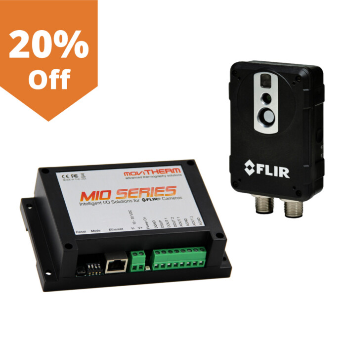
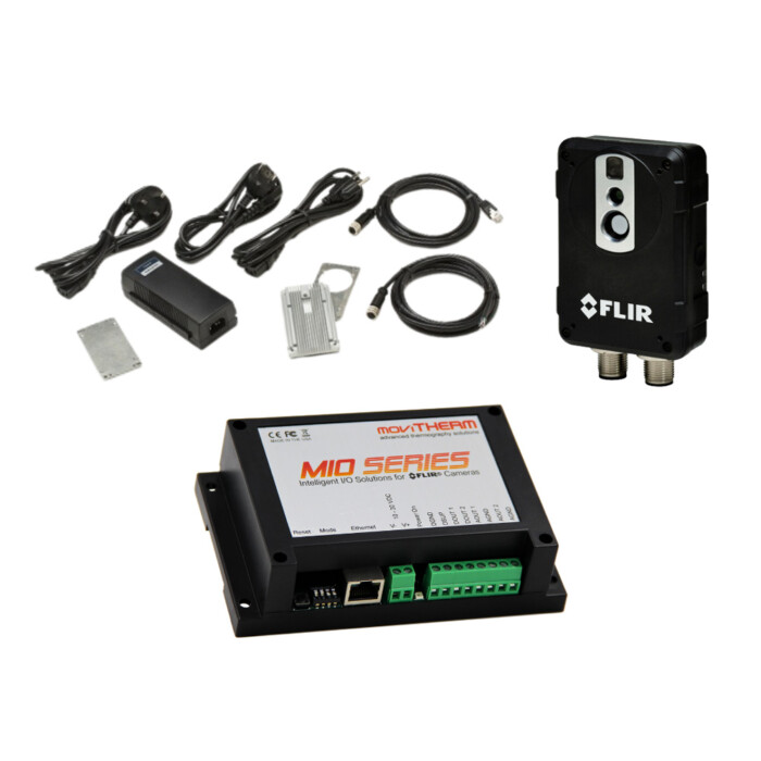
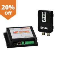
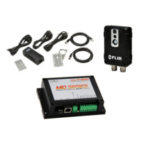
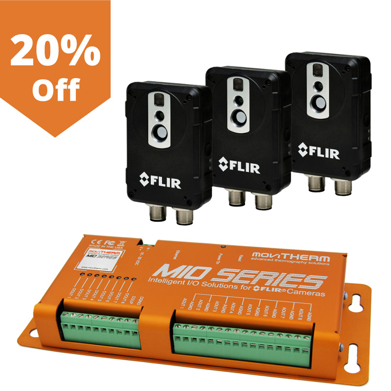
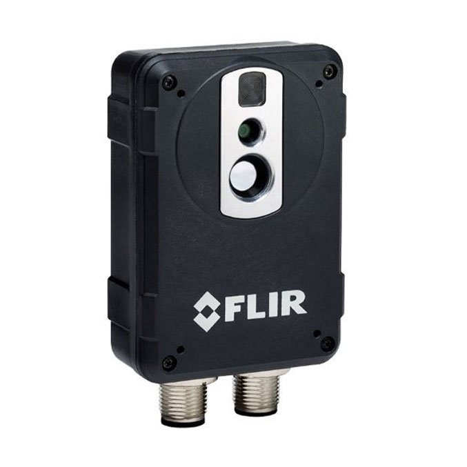
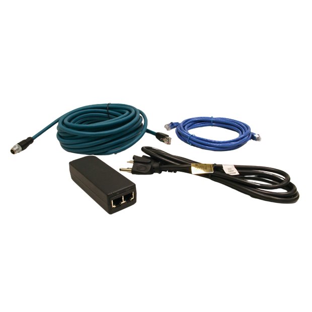
FLIR AX8 and MIO MAX-1 Single Camera Bundle
Guaranteed safe & secure checkout

We also accept ACH/wire transfer, checks, and purchase orders.
Web Interface
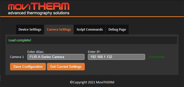 Sample Camera Configuration |
Easy Configuration via built-in Web-ServerThe MIO Series Intelligent I/O module comes with a built-in web-server for easy configuration. No additional software is needed to setup your thermal monitoring system. The web-server interface is intuitive. Simply add the IP address of each of the connected FLIR cameras. |
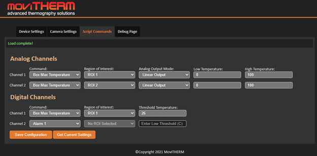 Sample Configuration |
The Script Commands TabAfter the camera settings have been entered and saved, the next task is to set up the script commands that create the intended system responses. The Script Commands tab is used to configure the commands configuration. |
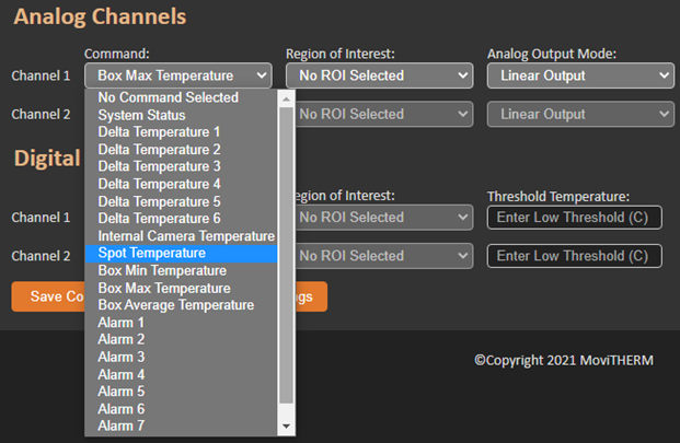 Command pull-down menu options |
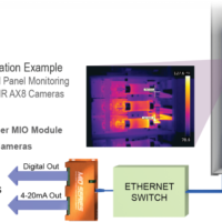
Command OptionsYou can customize the outputs (digital and analog) for each camera. For instance, if you have four regions of interest in one camera, you can assign two analog and two digital outputs to each region, each with its own alarm threshold. Alternatively, you can use the analog 4 to 20mA outputs for external monitoring or control. If you need more outputs, simply add another MIO I/O module to expand your system. |
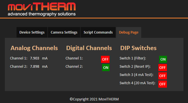 The Debug Tab shows the current output state of each MIO Board output channel, and the DIP switch states |
The Debug TabAfter the configuration has been defined, the Debug Tab provides a convenient, interactive window into the real-time operation of the MIO Board. Using the Debug tab, you can observe the current status of all output channels and DIP switches at a glance. You can use this tab to validate output channel operations. |
Specifications
| FLIR AX8 Specifications | |
|---|---|
| IR resolution | 80 × 60 pixels |
| Thermal sensitivity/NETD | < 0.10°C @ +30°C (+86°F) / 100 mK |
| Field of view (FOV) | 48° × 37° |
| Focus | Fixed |
| Detector data | |
| Detector type | Focal Plane Array (FPA), uncooled microbolometer |
| Spectral range | 7.5–13 μm |
| Visual camera | |
| Built-in digital camera | 640 × 480 |
| Digital camera, FOV | Adapts to the IR lens |
| Sensitivity | Minimum 10 Lux without illuminator |
| Measurement | |
| Object temperature range | –10°C to +150°C (14°F to 302°F) |
| Accuracy | ±2°C (±3.6°F) or ±2% of reading (+10 to +100C@+10 to +35 amb) |
| Measurement analysis | |
| Spotmeter | 6 |
| Area | 6 boxes with max./min./average |
| Automatic hot/ cold detection | Max/Min temp. value and position shown within box |
| Measurement presets | Yes |
| Atmospheric transmission correction | Automatic, based on inputs for distance, atmospheric temperature and relative humidity |
| Optics transmission correction | Automatic, based on signals from internal sensors |
| Emissivity correction | Variable from 0.01 to 1.0 |
| Reflected apparent temperature correction | Automatic, based on input of reflected temperature |
| External optics/ windows correction | Automatic, based on input of optics/window transmission and temperature |
| Measurement corrections | Global object parameters |
| Alarm | |
| Alarm functions | Automatic alarms on any selected measurement function. A maximum of 5 alarms can be set |
| Alarm output | Digital Out, store image, file sending (ftp), email (SMTP), notification |
| Set-up | |
| Color palettes | Color palettes (BW, BW inv, Iron, Rain) |
| Set-up commands | Date/time, Temperature °C/°F |
| Web interface | Yes |
| Storage of images | |
| Storage media | Built-in memory for image storage |
| Image storage mode | IR, visual, MSX |
| File formats | JPEG+FFF |
| Ethernet | |
| Ethernet | Control, result and image |
| Ethernet, type | 100 Mbps |
| Ethernet, standard | IEEE 802.3 |
| Ethernet, connector type | M12 8-pin X-coded |
| Ethernet, video streaming | Yes |
| Ethernet, power | Power over Ethernet, PoE IEEE 802.3af class 0. |
| Ethernet, protocols | Ethernet/IP, Modbus TCP, TCP, UDP, SNTP, RTSP, RTP, HTTP, ICMP, IGMP, sftp, SMTP, SMB (CIFS), DHCP, MDNS (Bonjour) |
| Image streaming | |
| Image streaming formats | Motion JPEG, MPEG, H.264 |
| Image streaming resolution | 640 × 480 |
| Image modes | Thermal, Visual, MSX (IR-image with enhanced detail presentation) |
| Automatic image adjustment | Continuous |
| Power system | |
| External power operation | 12/24VDC, 2 W continuously/ 3.1 W absolute max |
| External power, connector | M12 8-pin A-coded (Shared with digital I/O) |
| Voltage Allowed range | 10.8–30VDC |
| Environmental data | |
| Operating temp. range | 0°C to +50°C (32°F to +122°F) |
| Storage temp. range | –40°C to +70°C (–40°F to +158°F) IEC 68-2-1 and IEC 68-2-2 |
| Humidity (operating and storage) | IEC 60068-2-30/24 h 95% relative humidity +25°C to +40°C (+77°F to +104°F)/ 2 cycles |
| EMC | EN 61000-6-2:2001 (Immunity) EN 61000-6-3:2001 (Emission) FCC 47 CFR Part 15 Class B (Emission) |
| Encapsulation | IP67 (IEC 60529) |
| Bump | 25 g (IEC 60068-2-29) |
| Vibration | 2 g (IEC 60068-2-6) |
| Physical data | |
| Camera size (L × W × H) | 54 × 25 × 79 mm (2.1 x 1 x 3.1 in.) w/o connectors 54 × 25 × 95 mm (2.1 x 1 x 3.7 in.) w/ connectors |
| Shipping information | |
| Packaging | Infrared camera with lens, printed documentation, user documentation CD-ROM |
Documentation
Description
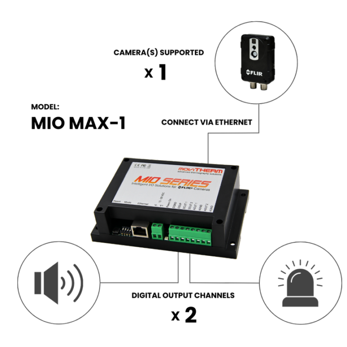
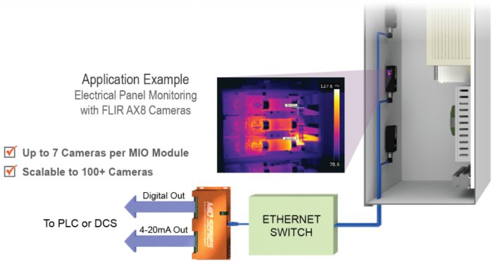
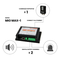
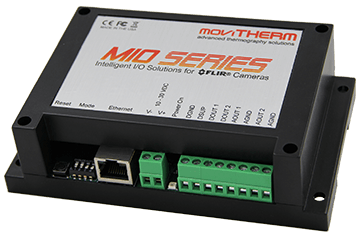
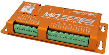
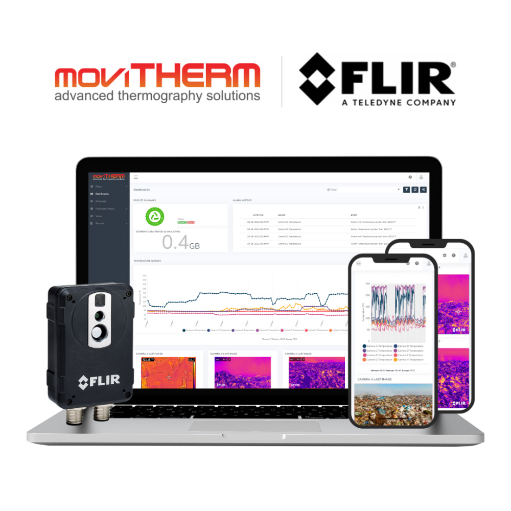
Are you looking for an easy way to turn your FLIR AX8 camera into a complete remote monitoring system? Introducing the NEW MIO Max Intelligent I/O Module, your hassle-free solution for remote monitoring setup and configuration. Simply connect your thermal cameras via Ethernet and easily set temperature alarm thresholds for each camera using a user-friendly web interface.
Customize your digital and analog outputs however you need, whether it’s assigning one alarm output per camera or using multiple outputs for a single camera. With MIO MAX, you have the power to tailor your remote monitoring setup to your exact needs.
MIO MAX Highlights:
- Compatible with FLIR AX8, A50/A70, and A400/A500/A700 smart cameras
- Convenient interchangeable camera connections within a single module
- Simple to set up with Ethernet connectivity
- Configure alarms via user-friendly web interface
- Scalable solution, up to 100+ Cameras with additional MIO unit
FLIR AX8 Highlights:
- 80 x 60 pixels IR resolution
- Field of view: 48° × 37°
- Fixed focus
- Object temperature range: –10°C to +150°C (14°F to 302°F)
- Built-in digital camera (640 x 480)
- Built-in memory for image storage

