Set up an Inspection Region on a FLIR A310 Camera
This video shows you how to set up an Inspection Region on your FLIR A310 camera.
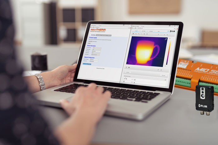
The MoviTHERM MIO Series – Intelligent I/O Module for FLIR® Cameras – supporting one of the following Camera models: FLIR AX8, FLIR FC Series R or FLIR A310
Remote Monitoring Applications Made Simple
More info about the MoviTHERM MIO Series Intelligent I/O Modules
Before you can use the MIO to detect and respond to temperatures, you first need to set up an inspection area or “region of interest” in the image. This video shows you how to set up that “region or interest” (or ROI) using the FLIR IR Monitor software. But before we can move on with this video, be sure to confirm that:
1) you have FLIR IR Monitor software installed on your PC, and
2) your A310 camera is able to communicate with your PC over an Ethernet connection
If you are not familar with the FLIR IR Monitor software, you can find the installation files on a disk that ships with the A310 camera. If you are unsure about how to assign an IP address to your A310, please refer to the video in this series devoted specifically to setting the A310’s IP address.
Ok, if you have IR Monitor software installed and are communicating with your camera over Ethernet, you are ready to go. The first step is to launch the FLIR IR Monitor application. If this is the first time running the software, you will need to start by selecting the camera. Click in the IR Monitor window to open the Camera Selection Dialog. All connected cameras will appear in the “Available Cameras” pane on the left. (If you have multiple cameras connected, you should see all of the cameras in the “Available Camera” list.)
Select the camera you would like to configure, then click and drag it to the “Camera Grid” region on the right. Next, click “View Cameras in grid” to exit the dialog and switch to the live camera view.
In the Live View mode, you should see a thermal image on the left, and various controls on the right. Let’s go ahead and change to color palette mapping to the Ironbow palette to enhance the visualization. Pull down the Palette control and select “Iron”.
Next, we need to focus the camera. Proper focus is just as important when using thermal cameras, because a fuzzy, out-of-focus thermal image will not report temperatures accurately. Autofocus is often all you need, so try this first. If the autofocus image isn’t as sharp as you like, you can manually fine-tune the focus with the “Near” and “Far” buttons.
When you are satisfied with the focus, click the Analysis tab to get to the Region set-up tools. By default, the camera has one “Spot” region defined. The MIO can monitor “Spot” regions, but for this example want to monitor an Area region. So let’s start by switching OFF the Spot1 region. Click “Spot 1” in the list, and click “Edit” to open the region editing dialog. Uncheck the “Show Spotmeter” parameter and click “Apply” to switch off the Spotmeter, and “OK” to exit.
Next, we want to set up Area 1 as our region of interest or “ROI”. Select “Area 1” and click “Edit”. Check the “Show Area” parameters to enable the new region. If you want to overlay the Maximum and Minimium temperatures from the region over the image, select “Both” from the “Show Max/Min” pulldown menu. Click “Apply” to enable the overlay region in the image.
You can use the “Position” and “Size” parameters to fine-tune the size and position of the region. Click “Apply” to update the overlay as you go. When you are satisfied with the region, click OK to close the dialog box. You can now see the region overlay on the image, along with the hotest and coldest points in the region.
Close IR Monitor to exit. Now you are ready to configure the MIO to respond to temperature changes in the region you have defined. That’s all you need to do to setup a Region of Interest on your FLIR A310 camera!
For more information on how to configure the MIO to work with this region, refer to other videos in this series. The videos about how to set up a 4-20mA Temperature Range output and how to setup a Digital Output Alarm demonstrate the steps.
View the other how-to videos in this series for additional tips on setting up your MIO system!
About MoviTHERM:
MoviTHERM – Advanced Thermography solutions was founded in 1999. The company offers solutions for plastic welding, package sealing, and non-destructive testing. In addition, MoviTHERM provides IoT Cloud monitoring solutions for thermal imaging applications for early fire detection, machine condition monitoring, and other applications. MoviTHERM is a Teledyne FLIR Premium Partner and master distributor for FLIR Thermal Cameras for automation and science applications.